
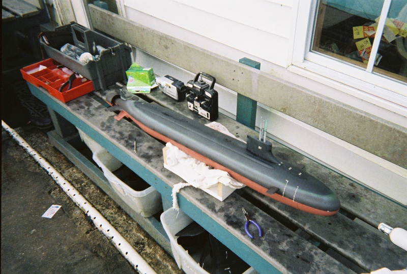
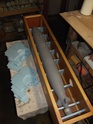
I've long had a glass reinforced plastic/fiberglass (GRP), resin and white-metal Precision Pattern (http://www.precisionpattern.biz/subs/index.htm) 1/96 SEAWOLF kit. Ten years ago I only got as far as hull half alignment and basic clean-up work on the appendages, sail and hull. I'm starting this WIP article with the GRP hull and sail done to the point of primer, and the Sub-driver (SD) installed. Jobs remaining include appendage attachment, control surface linkage integration, installation of the snorkel mechanism, fixed ballast and buoyant foam (this is a wet-hull type r/c submarine), and creation of a new rotor.
I've taken on the project again with intent to finish it in time for the 1/96 fleet run this October in North Carolina -- I want this guy to join my fleet of other 1/96 scale r/c submarines there.
I'm no stranger to this particular product: previously I assembled and made RTR two of these kits for customers. So, this one ... MINE!! .... is a cake-walk.
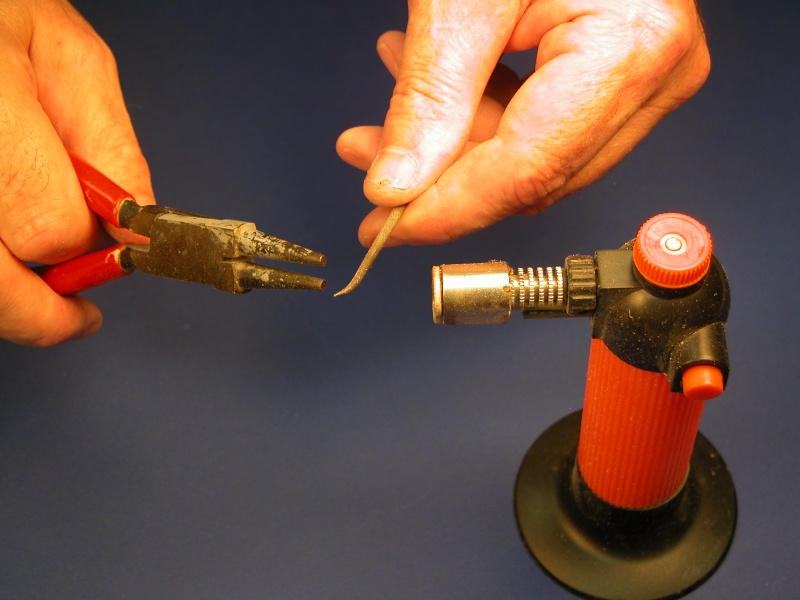
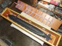
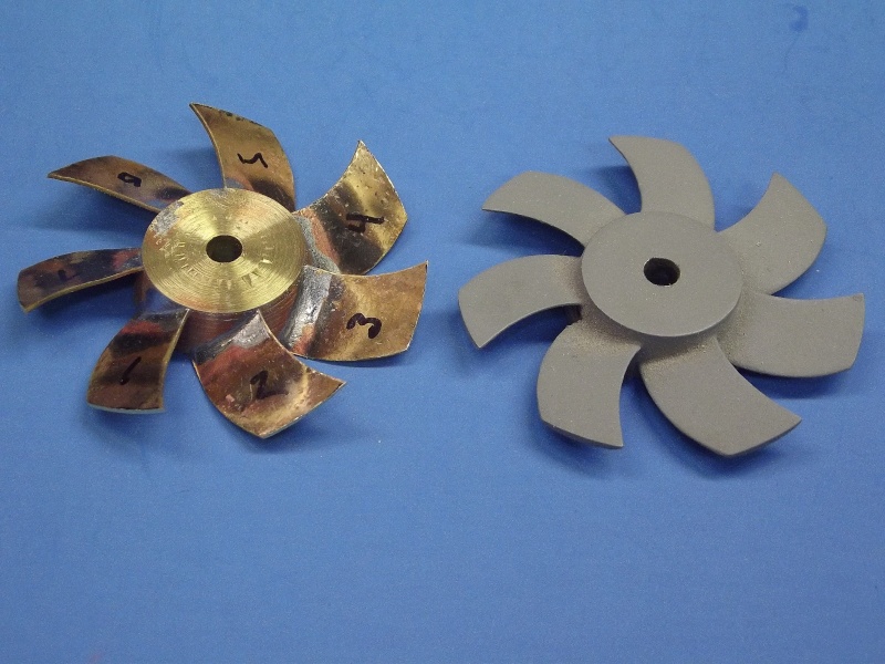
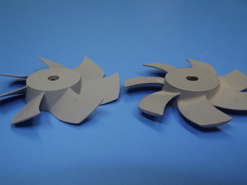
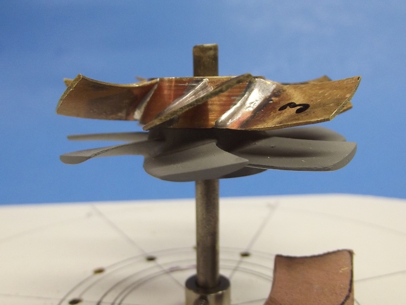
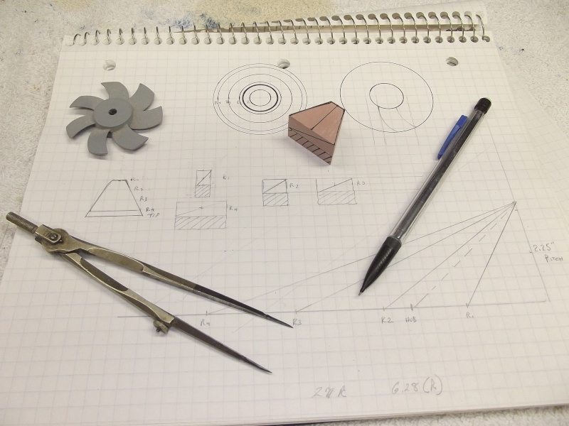
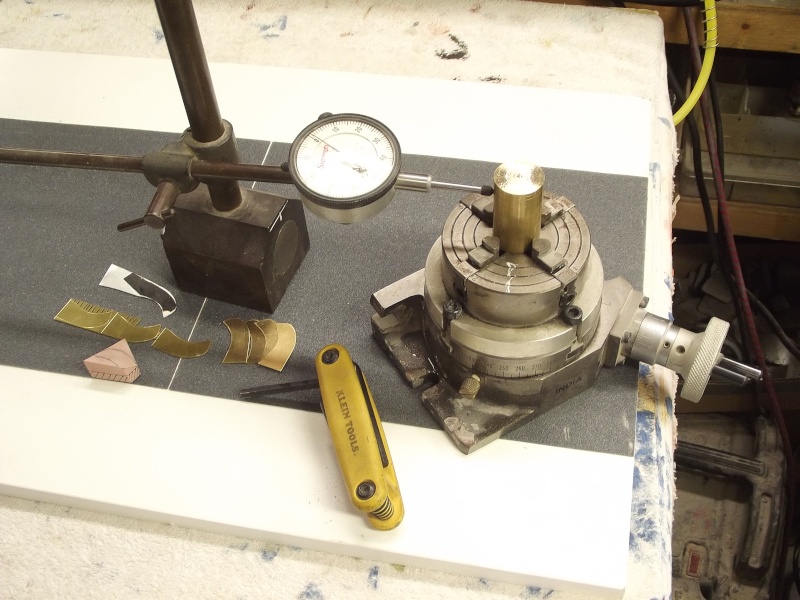
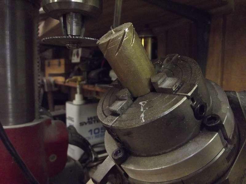
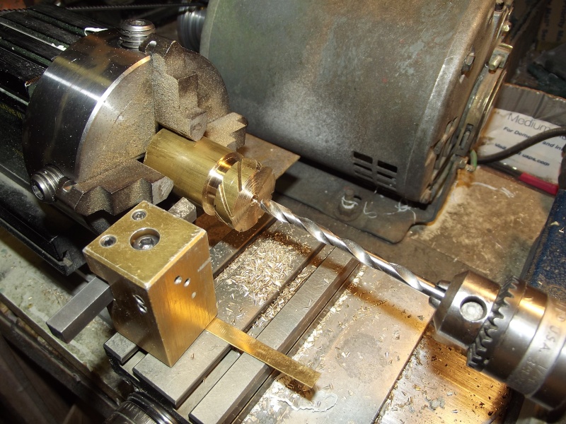
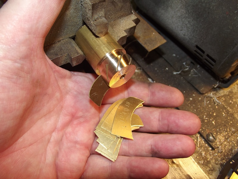
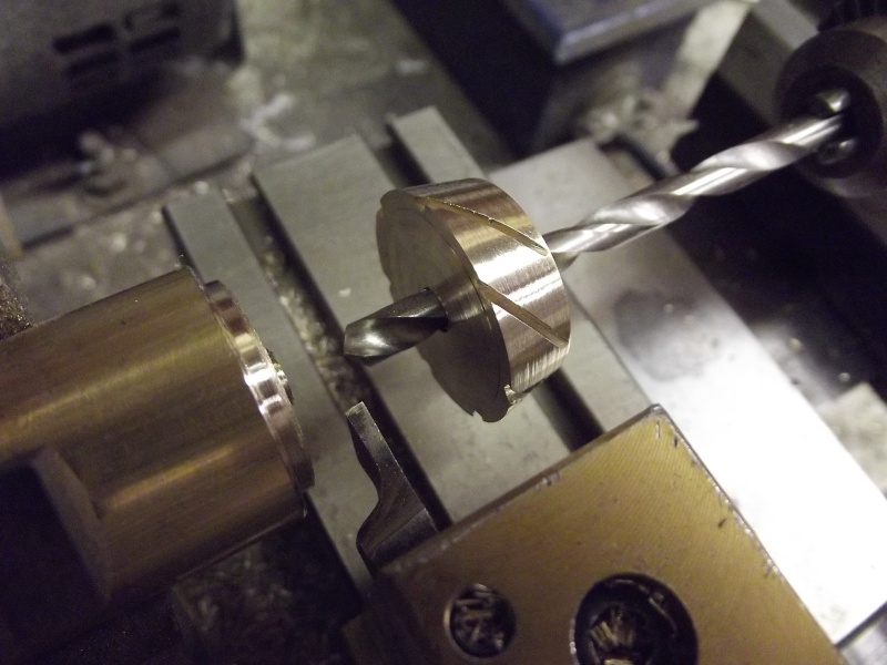
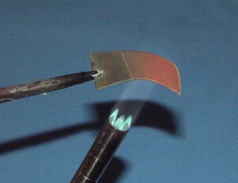
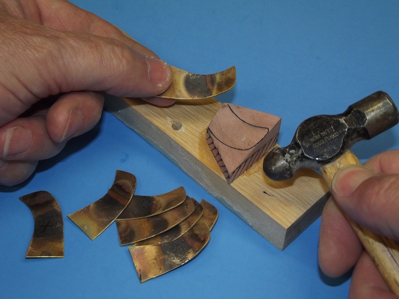
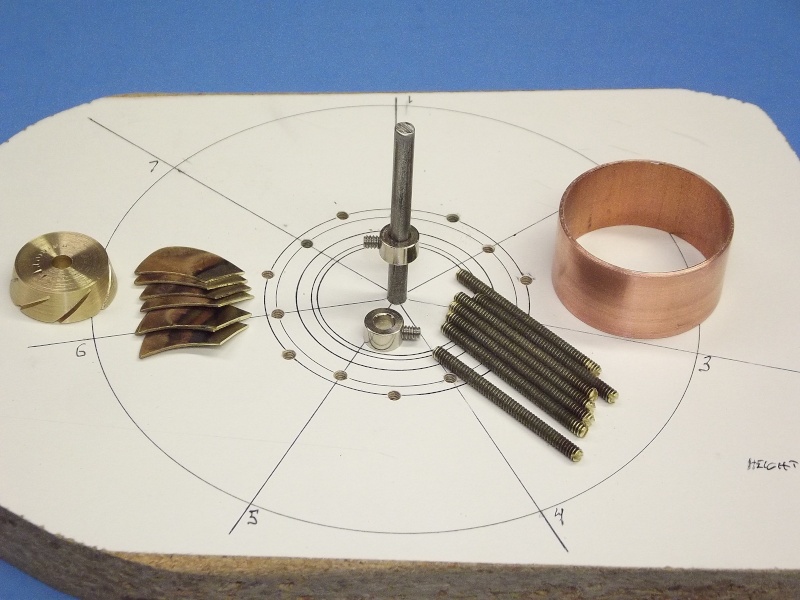
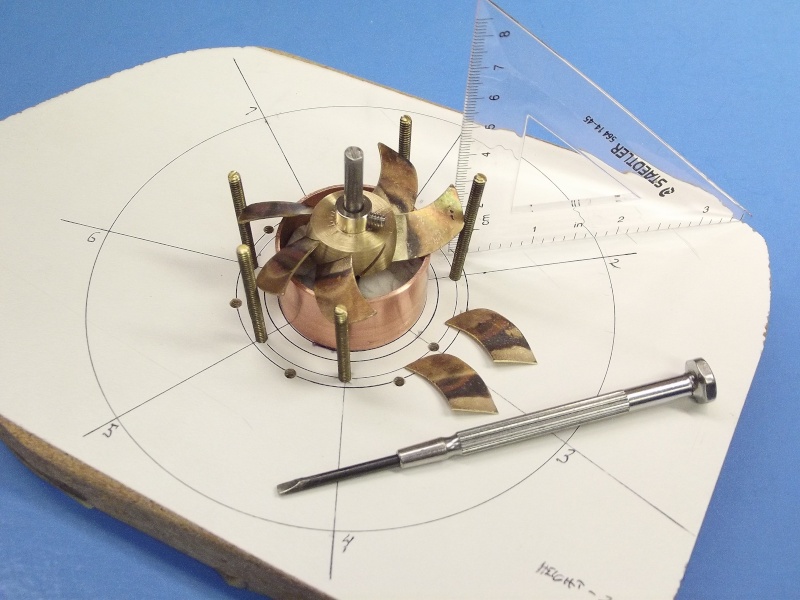
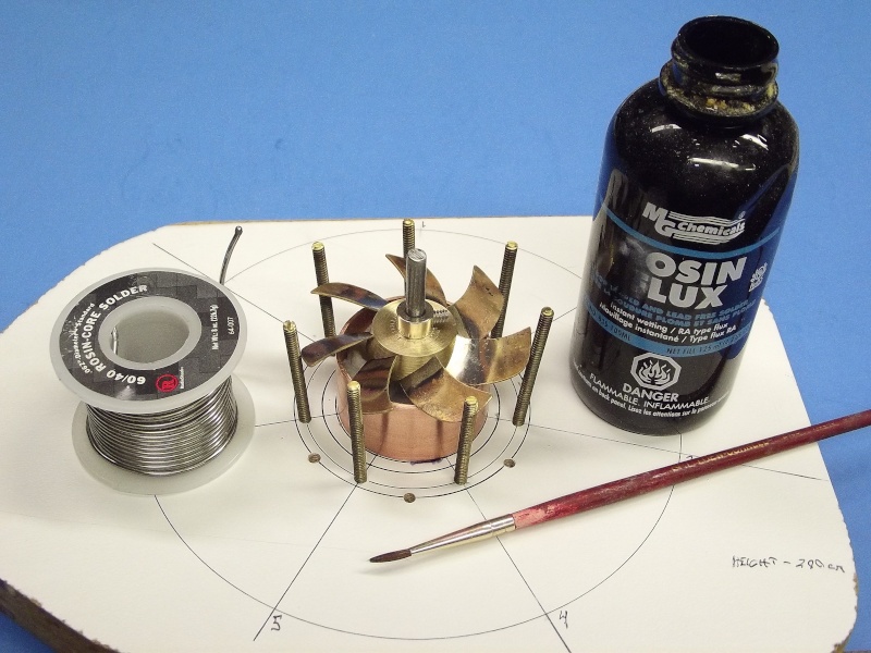
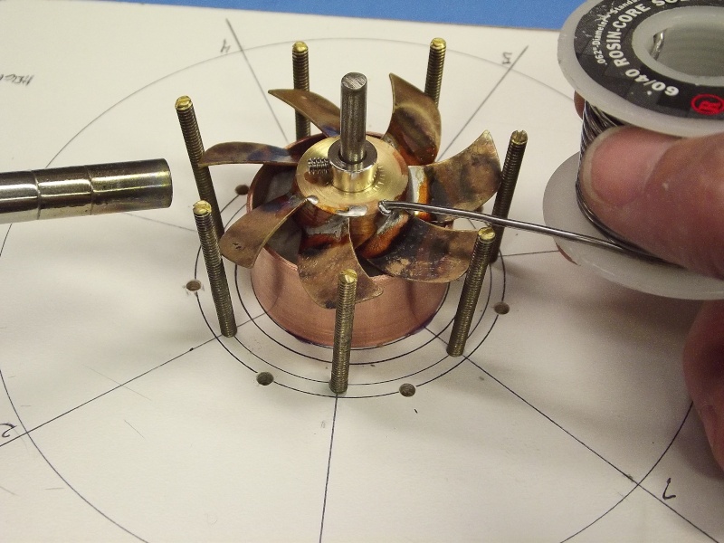
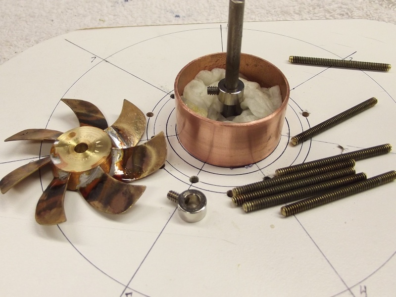
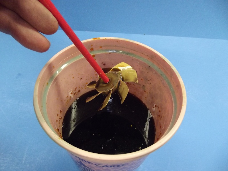
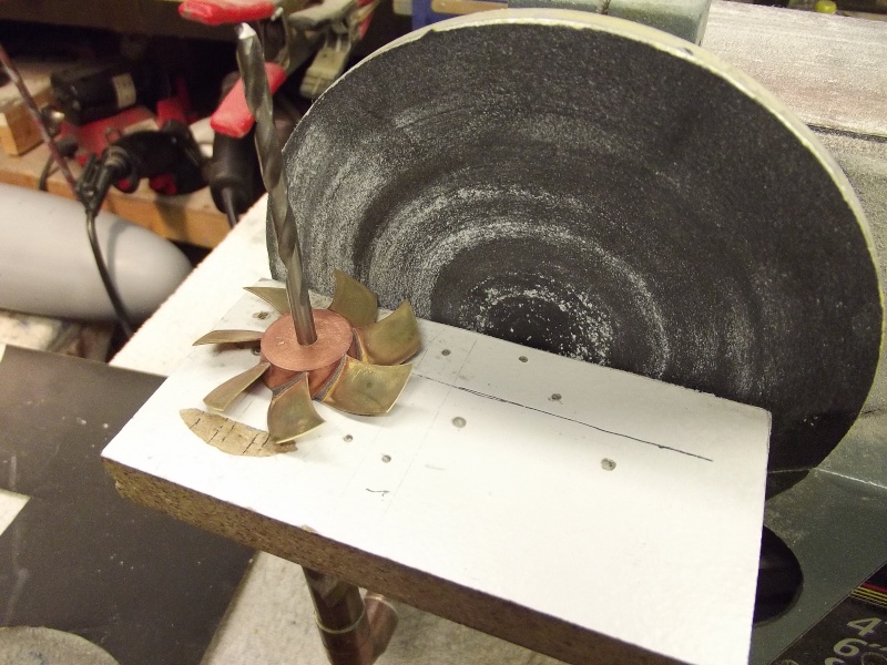
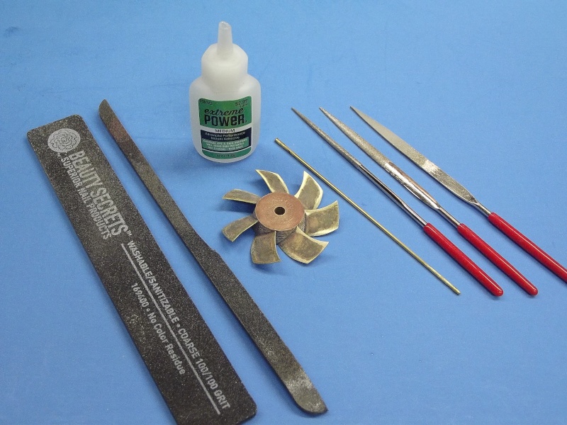
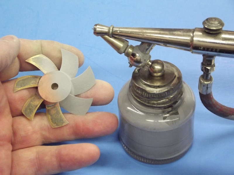
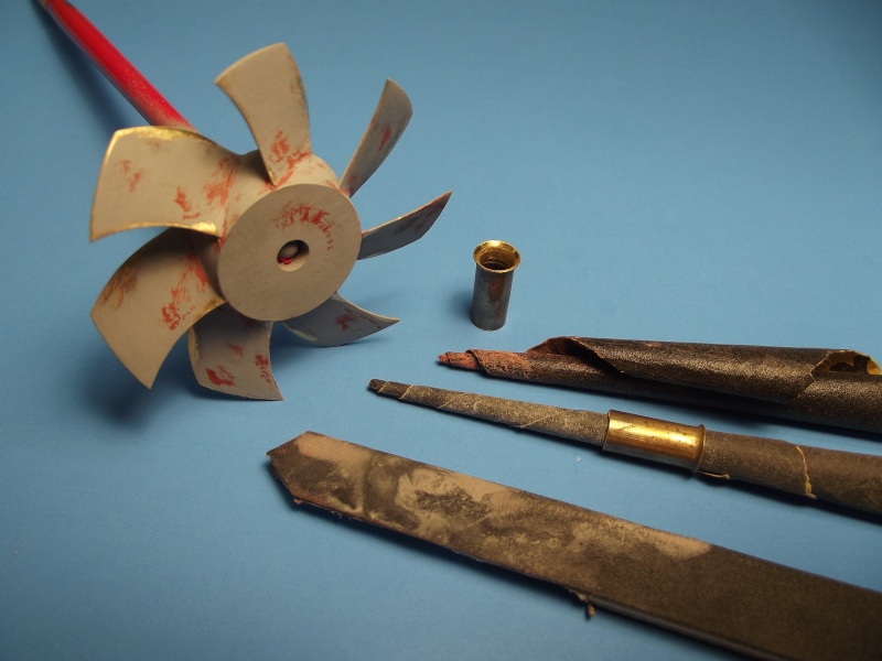
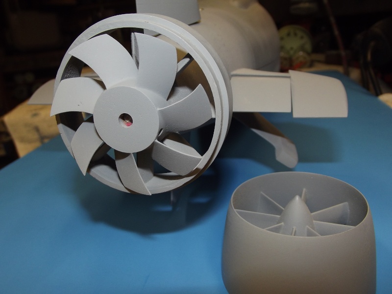
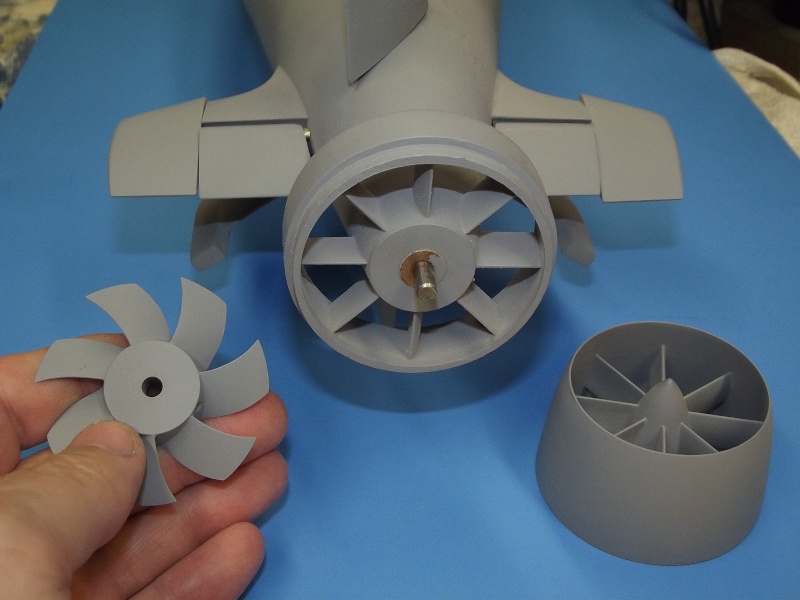
The Precision Pattern 1/96 SEAWOLF kit features the usual exceptionally high standard of glass layup on the hull parts, and bubble free resin pieces this outfit is known for. However, the rotor for the pump-jet (PJ) is awful -- way to short of pitch, so I'll solder together a replacement from cartridge-brass sheet blades and a turned machine-brass hub.
[IMG]file:///C:/Users/David/AppData/Local/Temp/msohtmlclip1/01/clip_image002.jpg[/IMG]
[IMG]file:///C:/Users/David/AppData/Local/Temp/msohtmlclip1/01/clip_image004.jpg[/IMG]
[IMG]file:///C:/Users/David/AppData/Local/Temp/msohtmlclip1/01/clip_image006.jpg[/IMG]
[IMG]file:///C:/Users/David/AppData/Local/Temp/msohtmlclip1/01/clip_image008.jpg[/IMG]
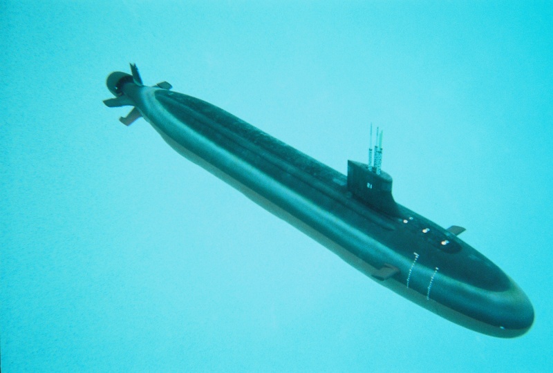
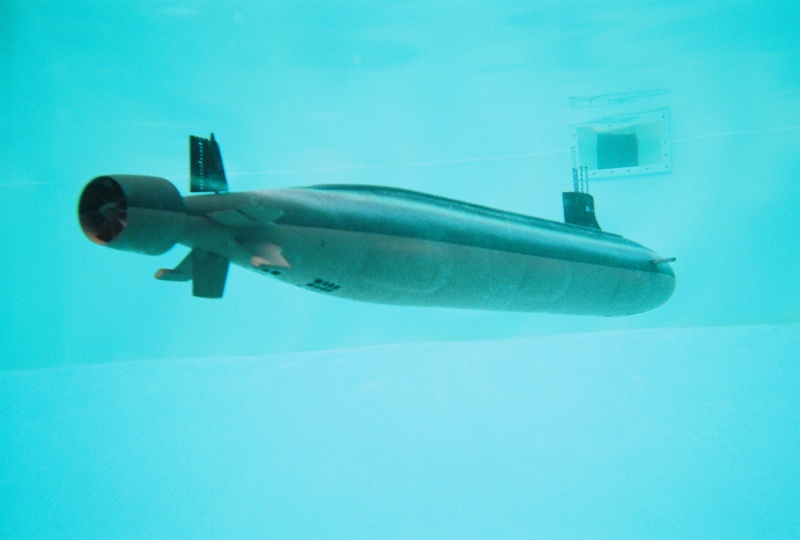
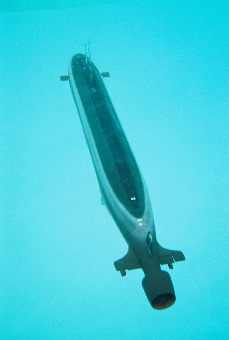
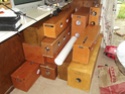
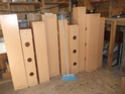
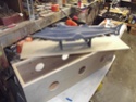
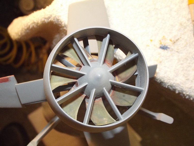
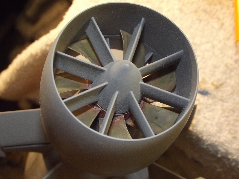
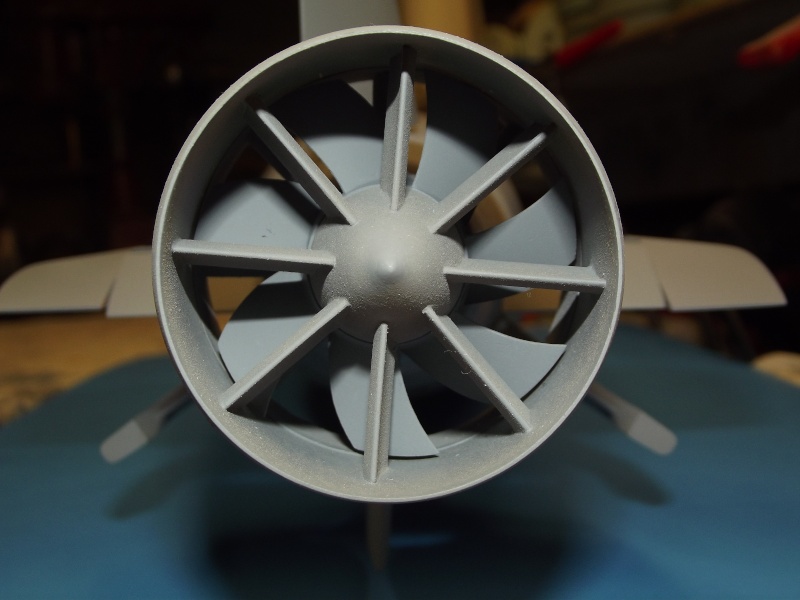
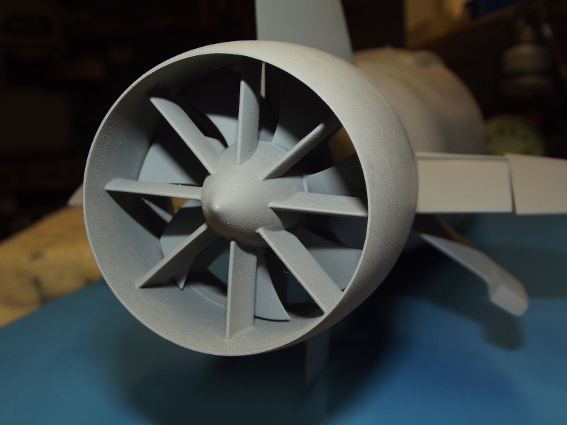
Some eye-candy for you -- shots of a RTR SEAWOLF assembled for a client. Just to give you an idea of the end-game of the article presented here. As to the performance of those commissioned models, using the kit supplied rotor: Slow; turned like molasses; and wobbly as to stern plane response; very good response to bow plane commands. Surfaced and submerged performance was, in a word, awful! The 1/96 sized model SEAWOLF's revealed themselves to be piglets in the water.
However, I anticipate that a new, higher pitch rotor -- driven by a 28-turn, five-pole 555 sized motor geared 3:1 -- will produce the thrust, and hence the speed, needed to give the stern planes and rudders more bite underway ... we'll see.
[IMG]file:///C:/Users/David/AppData/Local/Temp/msohtmlclip1/01/clip_image010.jpg[/IMG]
[IMG]file:///C:/Users/David/AppData/Local/Temp/msohtmlclip1/01/clip_image012.jpg[/IMG]
[IMG]file:///C:/Users/David/AppData/Local/Temp/msohtmlclip1/01/clip_image014.jpg[/IMG]
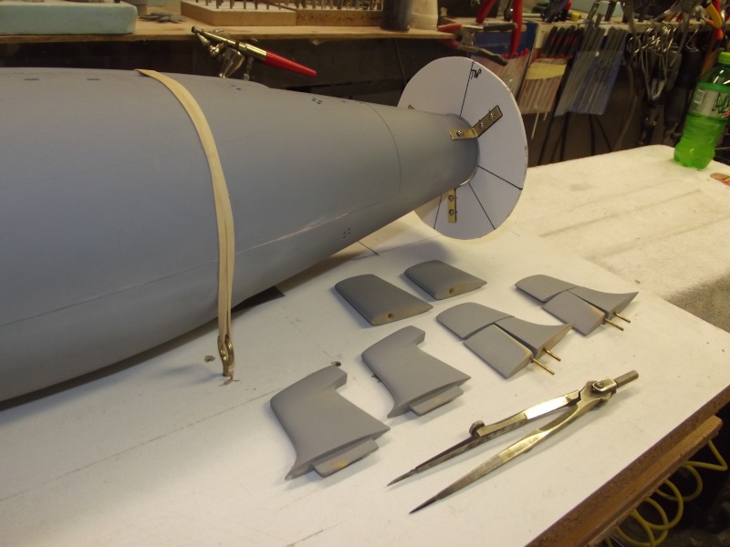
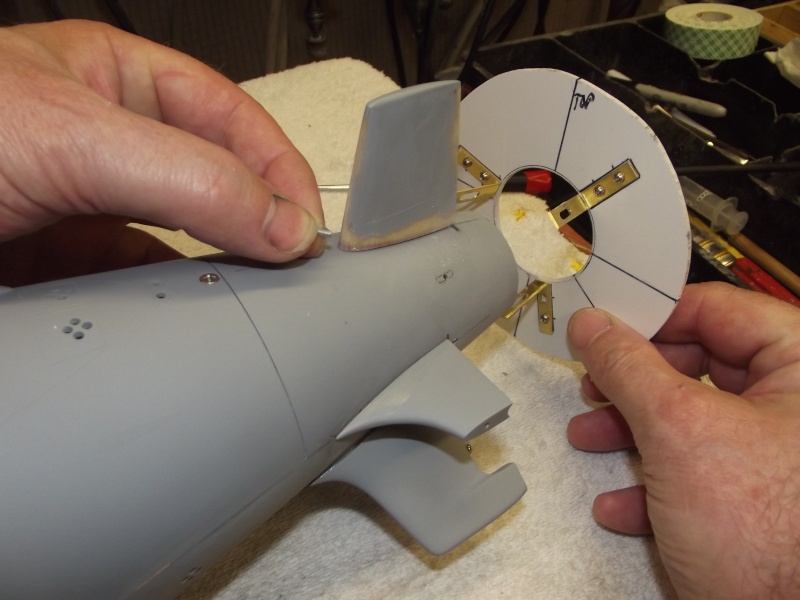
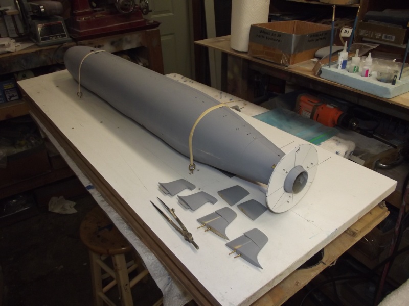
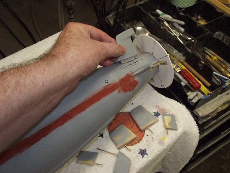
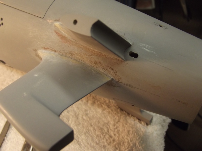
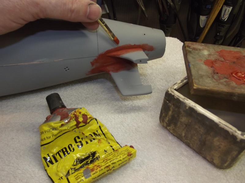
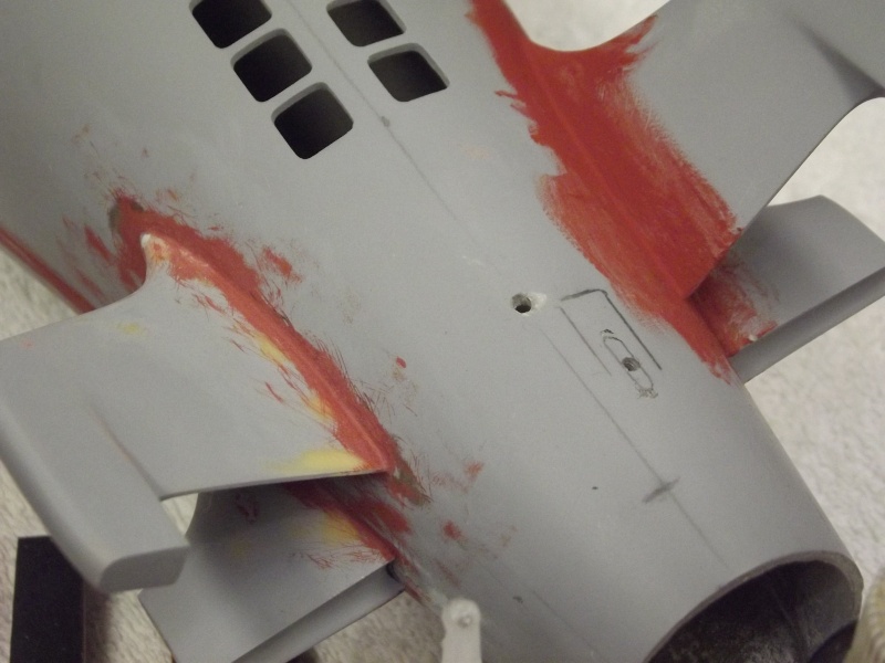
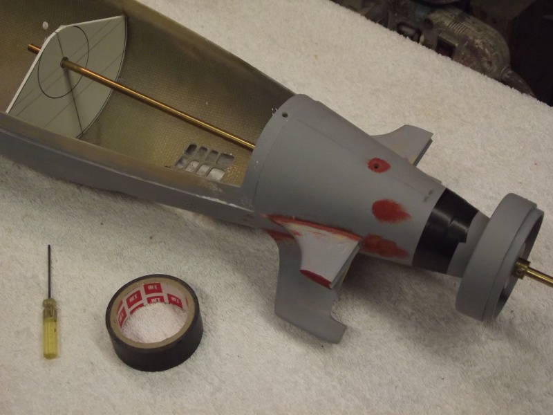
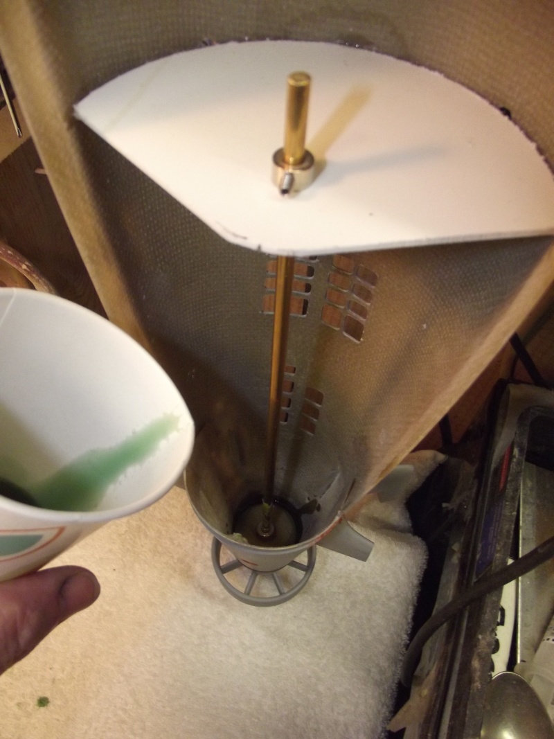
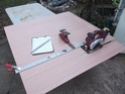
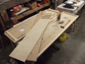
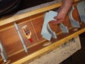
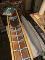
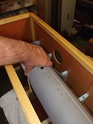
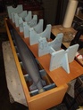
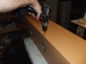
Cheat marks and lines molded into the hull denoted where to install the rudder shafts, horizontal stabilizers and anhedral stabilizers (the anhedral stabilizers work to counter the inboard roll resulting from submerged high speed turns). These identifying marks were a big help, but could not guide me as I worked to install these appendages perpendicular to the hulls longitudinal axis. So I made a hull mounted, disc-shaped appendage alignment fixture -- used to guide me as I lined up an appendage and CA'ed it in place.
[IMG]file:///C:/Users/David/AppData/Local/Temp/msohtmlclip1/01/clip_image016.jpg[/IMG]
[IMG]file:///C:/Users/David/AppData/Local/Temp/msohtmlclip1/01/clip_image018.jpg[/IMG]
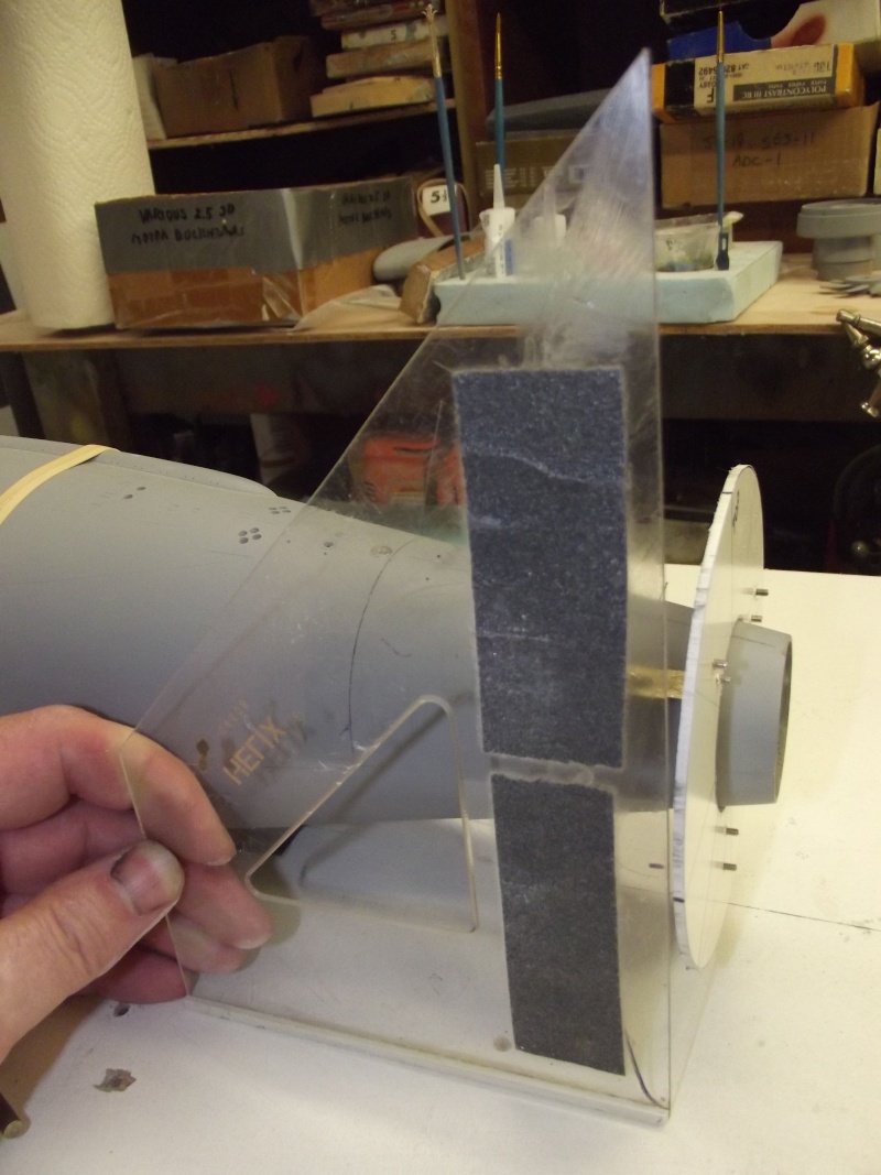
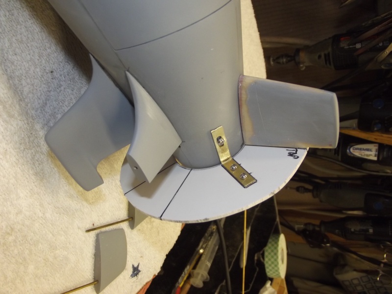
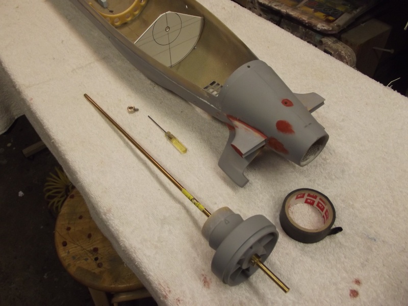
The appendage alignment fixture was temporarily secured to the after end of the hull by small machine screws passing through elongated holes within the brass straps that made up to the indexing fixture. This permitted adjustment of the fixture till its plane was perpendicular to the hulls longitudinal axis. The horizontal reference (datum) plane being a true work-table and the vertical plane established with a 90-degree tri-angle.
[IMG]file:///C:/Users/David/AppData/Local/Temp/msohtmlclip1/01/clip_image020.jpg[/IMG]
I've taken on the project again with intent to finish it in time for the 1/96 fleet run this October in North Carolina -- I want this guy to join my fleet of other 1/96 scale r/c submarines there.
I'm no stranger to this particular product: previously I assembled and made RTR two of these kits for customers. So, this one ... MINE!! .... is a cake-walk.
The Precision Pattern 1/96 SEAWOLF kit features the usual exceptionally high standard of glass layup on the hull parts, and bubble free resin pieces this outfit is known for. However, the rotor for the pump-jet (PJ) is awful -- way to short of pitch, so I'll solder together a replacement from cartridge-brass sheet blades and a turned machine-brass hub.
[IMG]file:///C:/Users/David/AppData/Local/Temp/msohtmlclip1/01/clip_image002.jpg[/IMG]
[IMG]file:///C:/Users/David/AppData/Local/Temp/msohtmlclip1/01/clip_image004.jpg[/IMG]
[IMG]file:///C:/Users/David/AppData/Local/Temp/msohtmlclip1/01/clip_image006.jpg[/IMG]
[IMG]file:///C:/Users/David/AppData/Local/Temp/msohtmlclip1/01/clip_image008.jpg[/IMG]
Some eye-candy for you -- shots of a RTR SEAWOLF assembled for a client. Just to give you an idea of the end-game of the article presented here. As to the performance of those commissioned models, using the kit supplied rotor: Slow; turned like molasses; and wobbly as to stern plane response; very good response to bow plane commands. Surfaced and submerged performance was, in a word, awful! The 1/96 sized model SEAWOLF's revealed themselves to be piglets in the water.
However, I anticipate that a new, higher pitch rotor -- driven by a 28-turn, five-pole 555 sized motor geared 3:1 -- will produce the thrust, and hence the speed, needed to give the stern planes and rudders more bite underway ... we'll see.
[IMG]file:///C:/Users/David/AppData/Local/Temp/msohtmlclip1/01/clip_image010.jpg[/IMG]
[IMG]file:///C:/Users/David/AppData/Local/Temp/msohtmlclip1/01/clip_image012.jpg[/IMG]
[IMG]file:///C:/Users/David/AppData/Local/Temp/msohtmlclip1/01/clip_image014.jpg[/IMG]
Cheat marks and lines molded into the hull denoted where to install the rudder shafts, horizontal stabilizers and anhedral stabilizers (the anhedral stabilizers work to counter the inboard roll resulting from submerged high speed turns). These identifying marks were a big help, but could not guide me as I worked to install these appendages perpendicular to the hulls longitudinal axis. So I made a hull mounted, disc-shaped appendage alignment fixture -- used to guide me as I lined up an appendage and CA'ed it in place.
[IMG]file:///C:/Users/David/AppData/Local/Temp/msohtmlclip1/01/clip_image016.jpg[/IMG]
[IMG]file:///C:/Users/David/AppData/Local/Temp/msohtmlclip1/01/clip_image018.jpg[/IMG]
The appendage alignment fixture was temporarily secured to the after end of the hull by small machine screws passing through elongated holes within the brass straps that made up to the indexing fixture. This permitted adjustment of the fixture till its plane was perpendicular to the hulls longitudinal axis. The horizontal reference (datum) plane being a true work-table and the vertical plane established with a 90-degree tri-angle.
[IMG]file:///C:/Users/David/AppData/Local/Temp/msohtmlclip1/01/clip_image020.jpg[/IMG]


Comment