-
Hey Joel.
As always the progress is great (even if you have had a set back). Keep on going.
Best
JLeave a comment:
-
So, here is where we are right now:
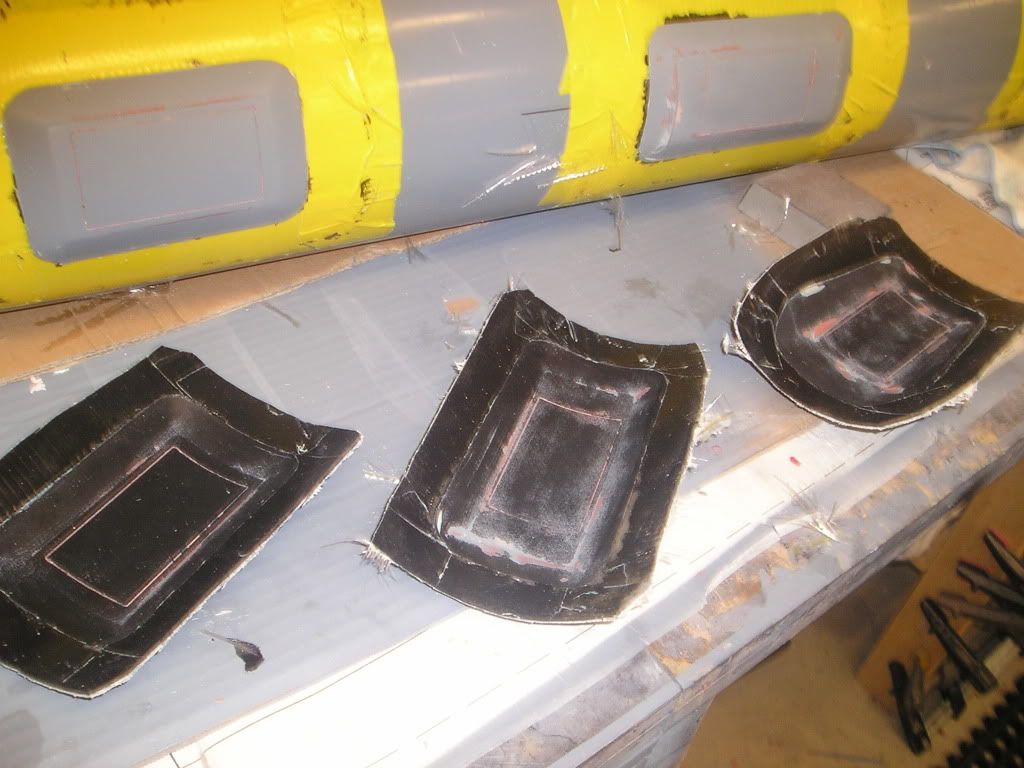
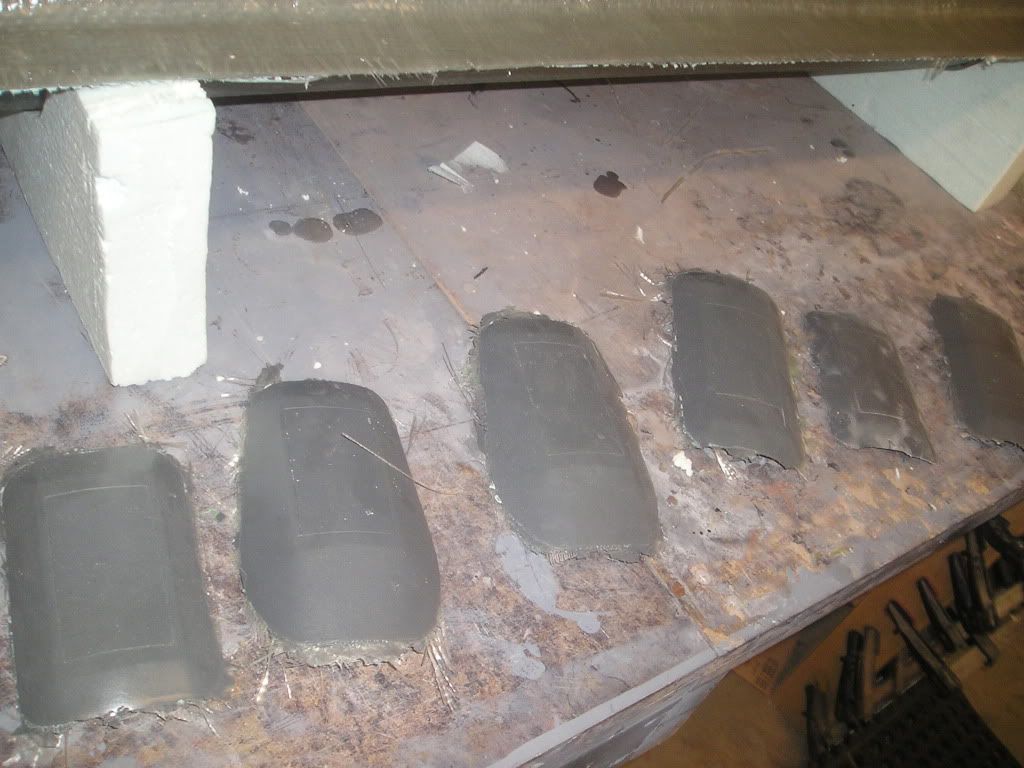
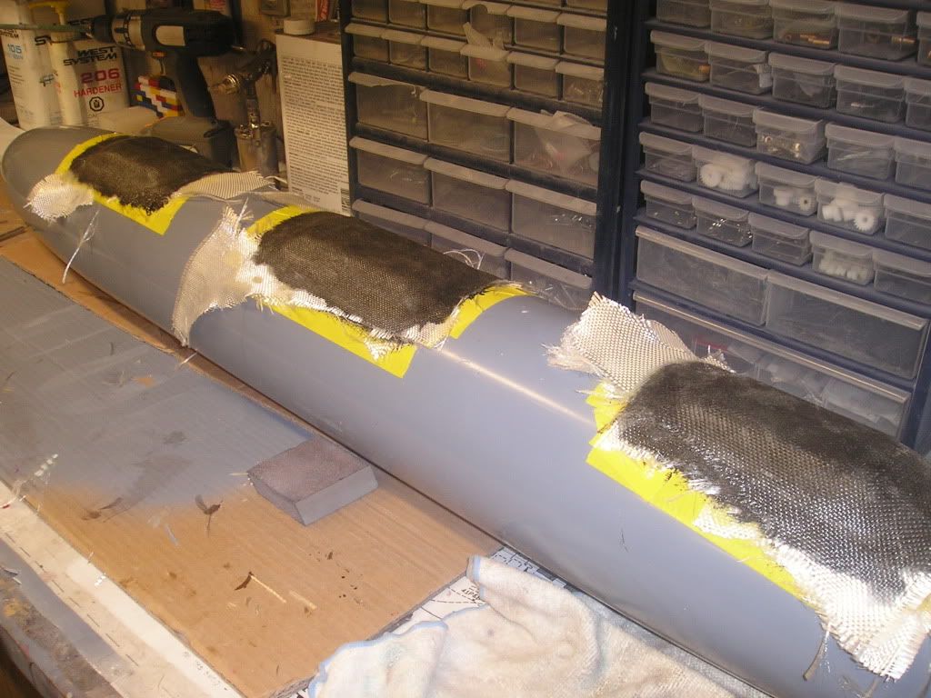
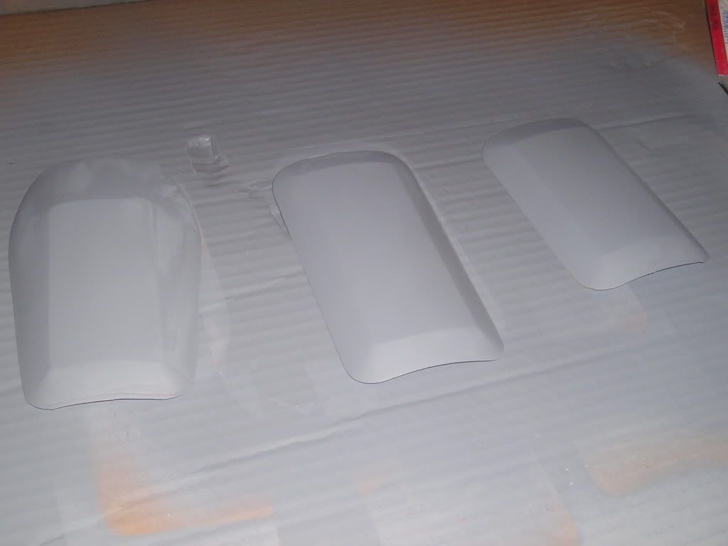
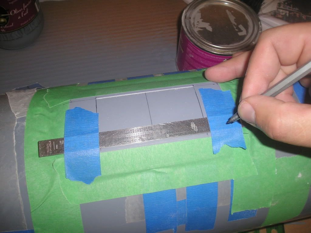
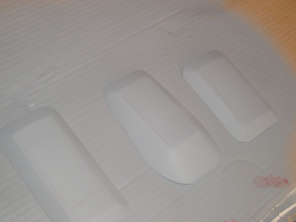
The WAA blisters were all moulded and reproduced, these are put off to the side until the bottom half of the hull master is ready for detailing. The only thing of note to mention about these is that I put an extra dense surface coat of epoxy and talc in the moulds before glassing. This coating should give me a nice hard surface in which to scribe into later, and yes I will need to scribe as we have all the pump suction and discharge grates to put on and the middle WAA sonar windows need to be redone because I made them the wrong length the first time.
Now, onto the stern planes and a description of what I have done here with these. In the beginning I made a single plane assembly that only had the plane demarcation break points scribed into it. I moulded that part and made three reproduction of it using some old crusty white Alumilite that has been sitting in my cupboard for the last year or so, perfect material for making master parts from. Each part was taped off along the lines in which they were to be separated from the rest of the plastic. The only exception here is I left a little extra material on the front the inside stern plane’s front edge because this will fit slightly into the stationary groove that will be provided on the stationary stern plane’s trailing edge.
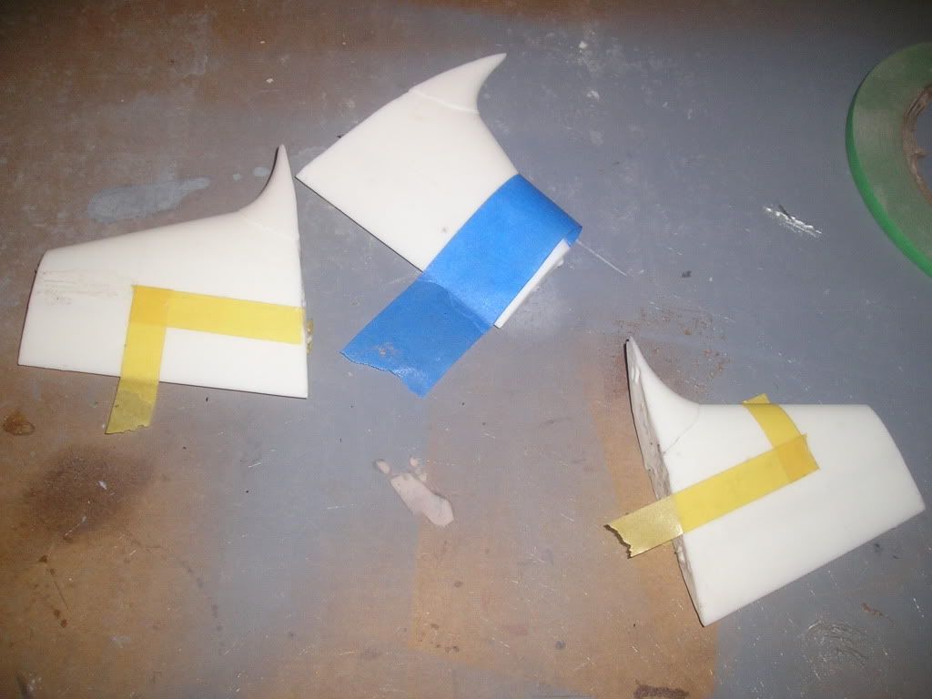
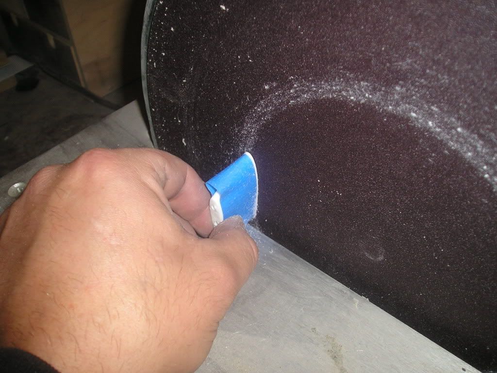
Each part was put in the vise (teeth grabbing the unused part of the plastic only) and then roughly hacksawed off. Trimming was done using my disc sander to remove plastic right up to where the tape was placed. Tape is a little better choice for this task as, believe it or not, it supplies a little protection from the possibility of removing too much material.
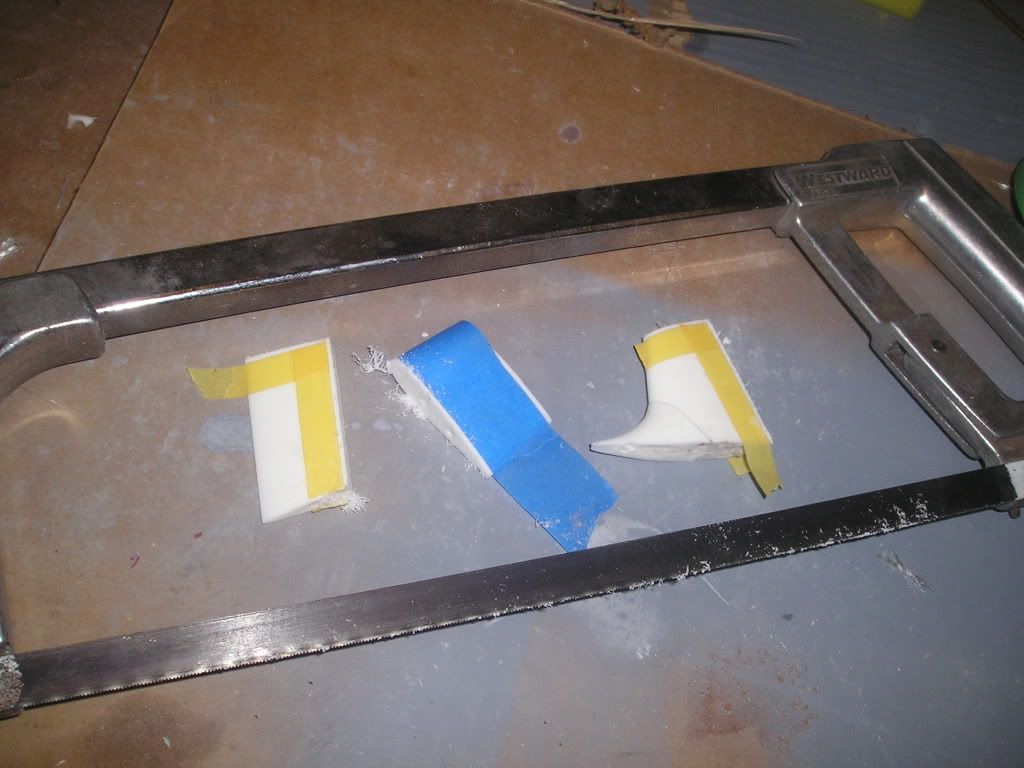
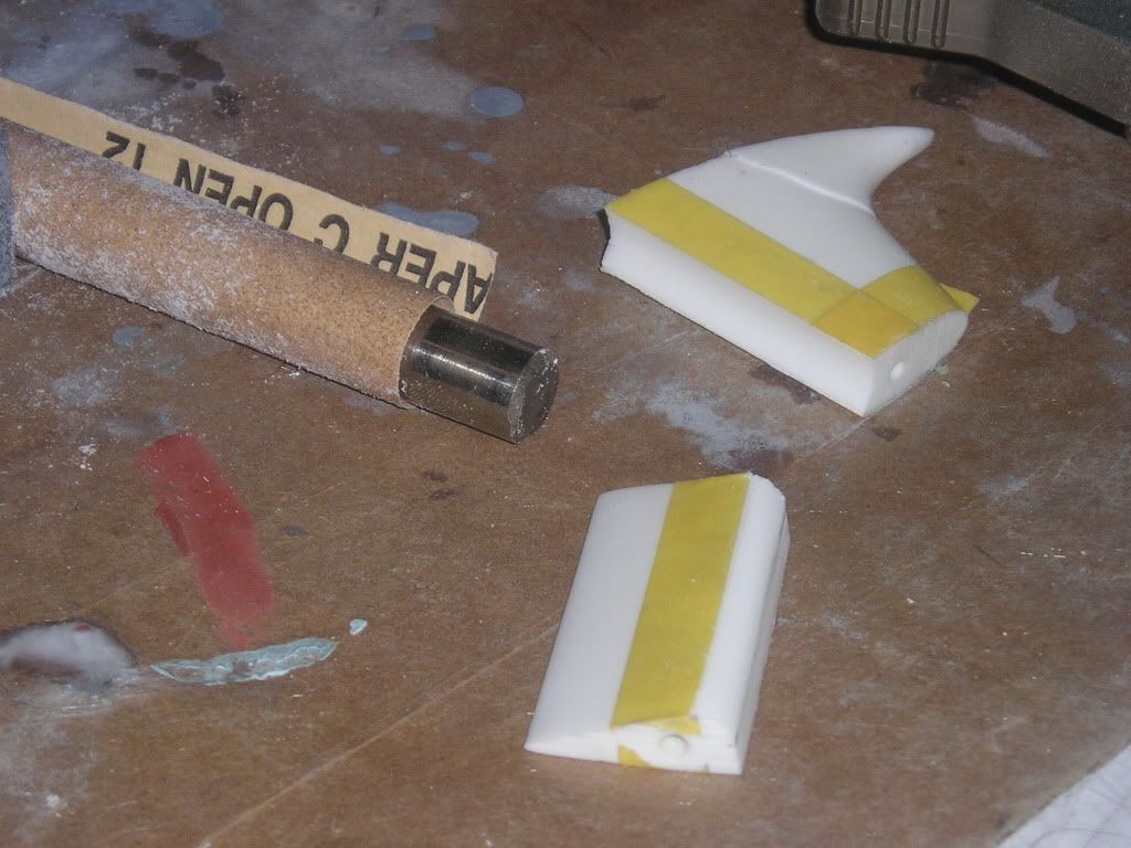
The trailing edge grove is put into the stationary plane by wrapping some tube of appropriate diameter in some coarse sandpaper and running the part back and forth along it. Very slick, very easy and the results were far better than when I used the drill press on my Permit parts to try and accomplish the same thing.
The rounded edge on the front of the inside stern plane was simply taped off at a point back from the front of the part and the center lined was drawn in on the middle length wise. From here, I block sanded the round shape in, using the tape and the center line to know my limits as to where to stop sanding.
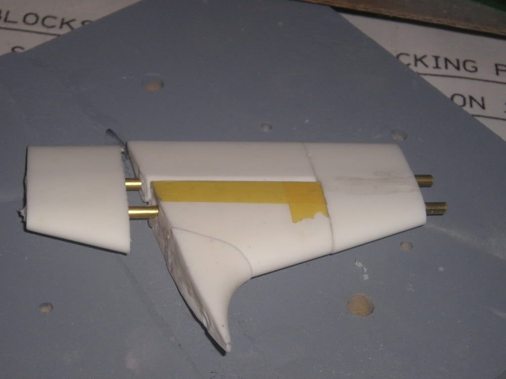
With the shapes roughly shaped, I then inserted 1/8 rod through them into the outside stern plane. At the bottom of the part i used a cut-off exterior plane and putt the rods into that for alignment check. How do I know that the shafts are straight though the planes? Because they fit perfectly into the outside planes, bottom and top perfectly...not even the slightest bit of pressure had to be applied to the rods to get them to fit, YAY!
To get the inside stern plane to have proper clearance and rotate smoothly within the stationary groove, sandpaper was slid in between the two part and slowly rocked the inside plane back and forth along it until I had fairly free move movement. The sandpaper was removed and I then had a perfectly shaped curved part that moved without inhibition with everything put on its proper shaft. Smooth.
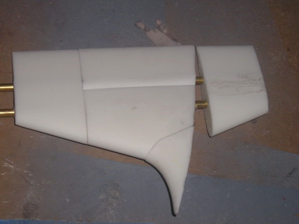
Now it’s just a matter of taping sandpaper to the hull where the plane will go and run the joining surface along that paper until the right size is achieved. I left the planes long actually with this in mind, but I still ended up going back and had to modify the fairing point in the front as it didn’t contact the hull properly.
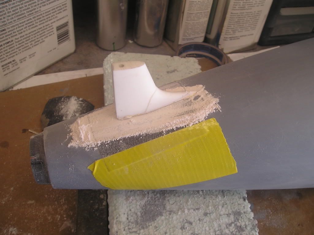 .
.
So where are we right now? Unfortunately, I had to go back and remake the intermediate hull moulds as they warped due to using two different manufactures products in their making. They were also too short because of some new, more accurate info I’ve received. An executive decision based on the reality that it easier to extend a single hull plug then to extend two half plugs and make them match properly...experience learned from my Jack project...The moulds are almost complete, so that means we can almost get into the negative detailing!
More to come,
JoelLeave a comment:
-
Hi Will,
The programs I have been using on my PC are:
Corel Draw
Corel Paint - these come as a suite known as X4 and are important because they use vectoring - the ability to make perfect circles no matter how much you shrink or blow them up. This is an extremely useful atribute for making the art for my photo etch art peices
Microsoft Paint
Microsoft picture manager
Adobe Acrobat professional - I use this for digital scaling and measuring for transfering to my models. I was quite surprised by how powerful this program is.
Obviously, the microsoft based programs can't be run on your mac, but i'm sure the Adobe and and Corel products can.
And oh yes, all hail the blue tape!
JoelLeave a comment:
-
Joel, You mentioned using several different imaging programs. Can you tell us which ones and whether there are versions for running on a Mac? By the way, you must use as much blue tape as I do. Thanks for sharing your tricks.
"Will" Rogers
SSBN659Leave a comment:
-
From here, I put a 600 grit wet sandpaper finish on the parts and prepare them for moulds. Some notes on these parts, I wouldn’t use styrene and Bondo again because it seems that Bondo doesn’t want to stick really well to it. I found myself gluing the joints repeatedly between sanding because the two materials would split. Another problem was that the primer I use eats the styrene profusely so that my clean, sharp edges melted away on the parts. This is ok though, I’m going to make moulds of the parts and reproduce them, then do all final finishing on those parts. Experience has told me that that even pristinely reproduced parts will still need some touch up and refinishing, so I’m not going to waste my time here on that.
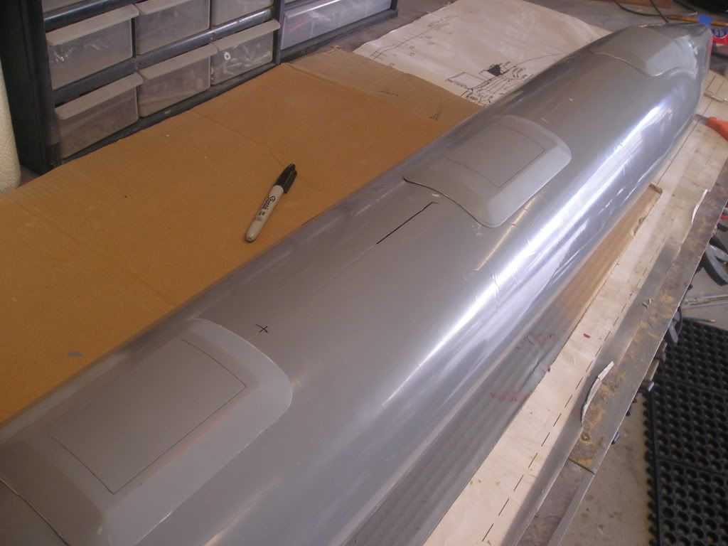
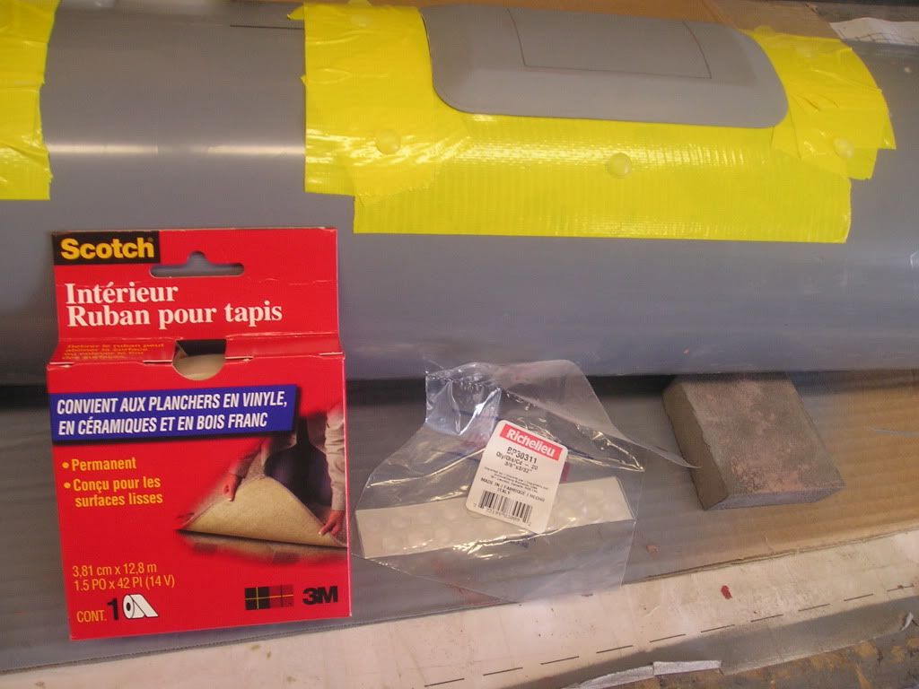
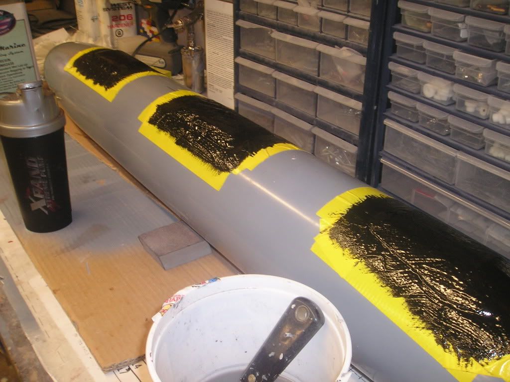
2 sided carpet tape to hold the WAA’s down to my plug hull. Also pictured are some cabinet bumpers I was going to use for registration nipples, but i changed my mind as I’m not to make the kind of mould that needs those yet. I’ll wait until my final hull mould ‘till I get into those
Leave a comment:
-
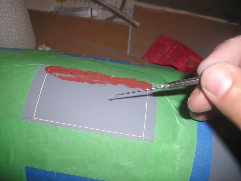
Inside the cardboard dams I filled with body filler (not Evercoat) that is fairly hard to sand and coloured with red cream hardener. This is trowelled along my profile ribs for proper shape. I made sure all block sanding was done before the filler was completely cured!
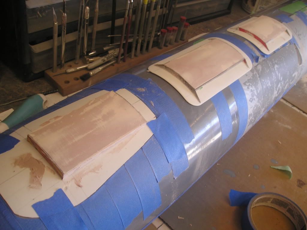
The long taper are added with an easy sand filler coloured with blue hardener
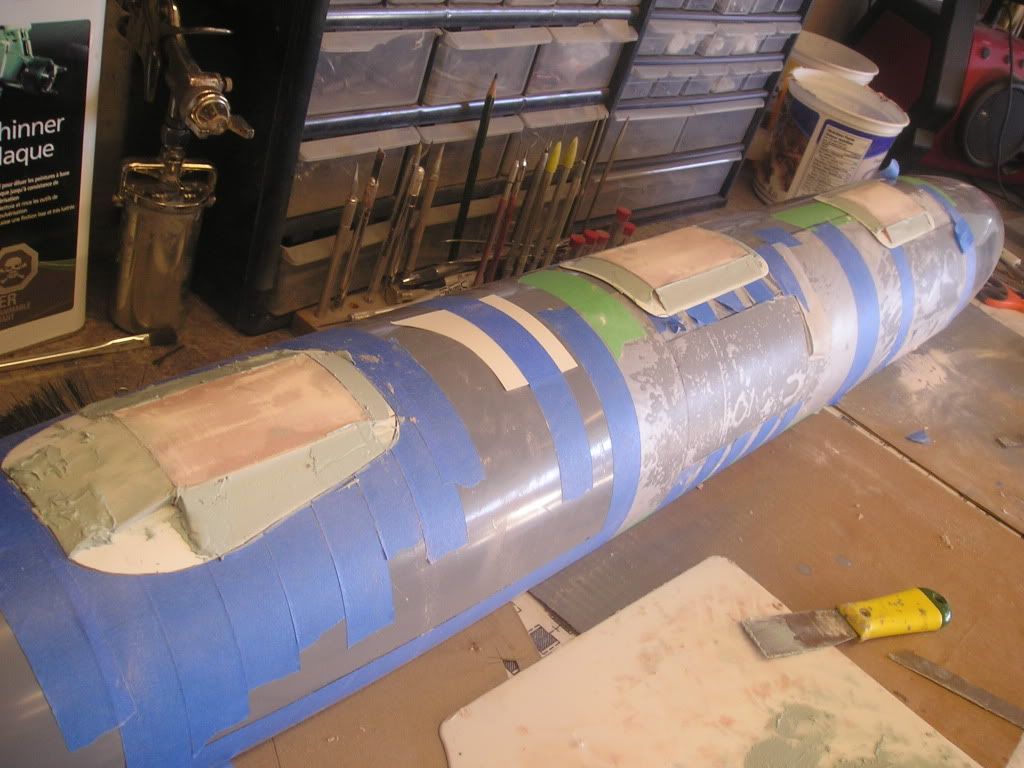
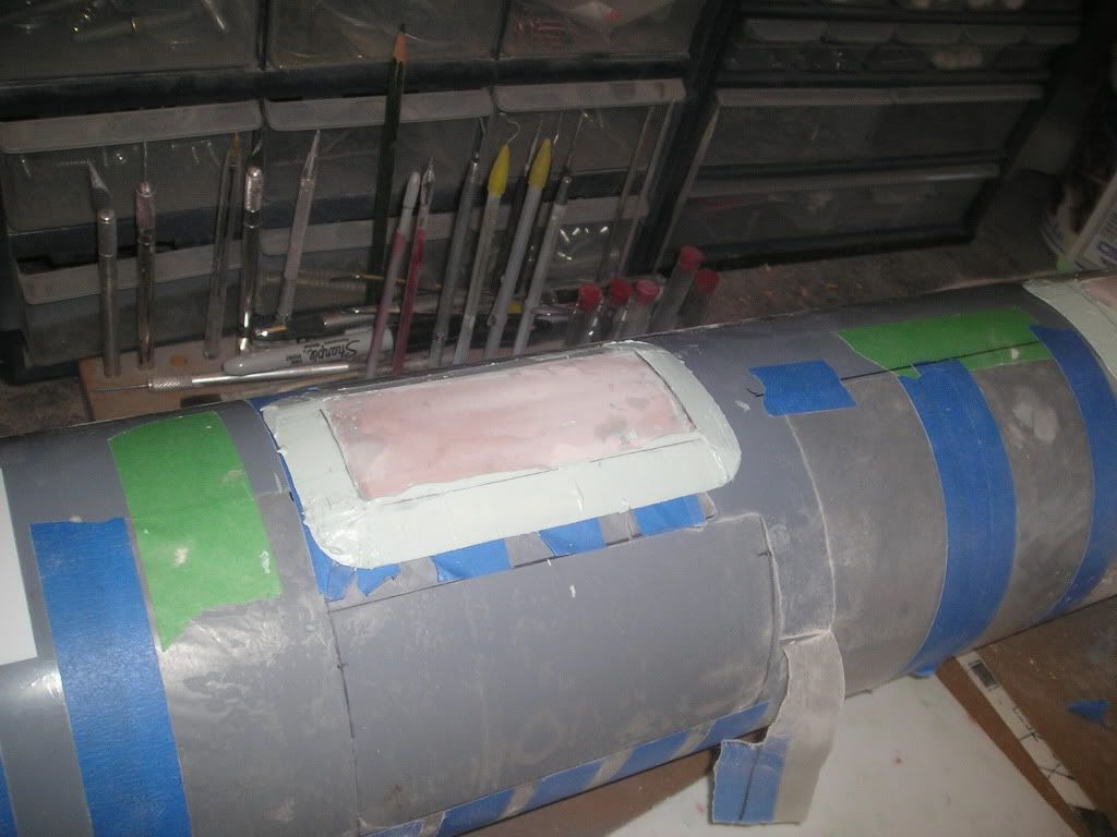
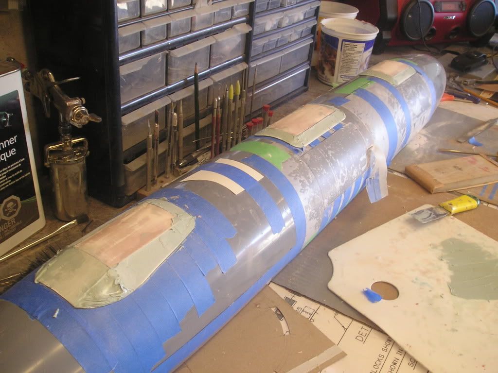
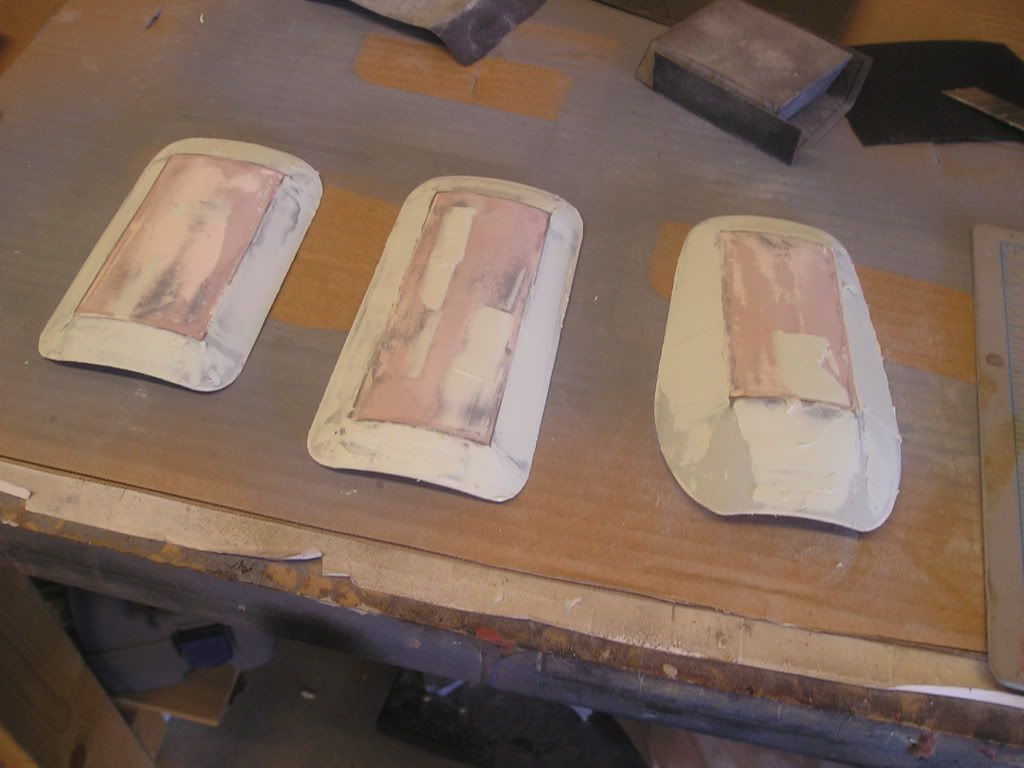
From there, its a matter of sanding, priming, filling, repeat over and over until happy with the shapes.
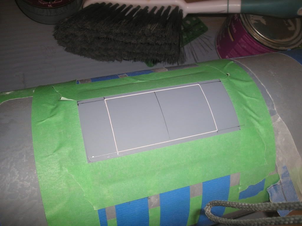
Next, I’ll scribe the sonar windows in
Leave a comment:
-
On to the wide aperture array blisters. These will be quite different than anything released so far in the Seawolf world. All three blisters on each side are different sizes and shapes from each other, with the farthest aft being the most different by far. In finding the right profile and shape for this bad boy I bet I have stared at blown up pictures for countless hours trying to get these figured out. In doing this I have incorporated the use of several different image manipulating programs so I can fiddle around and confirm the shape that I have always suspected.
Let’s get started. I made the decision to go with thin styrene for use in the base shapes of the WAA that goes against the hull. I don’t think I would use this material for this kind of application again and you will find out why as I delve further into the depths of this build.
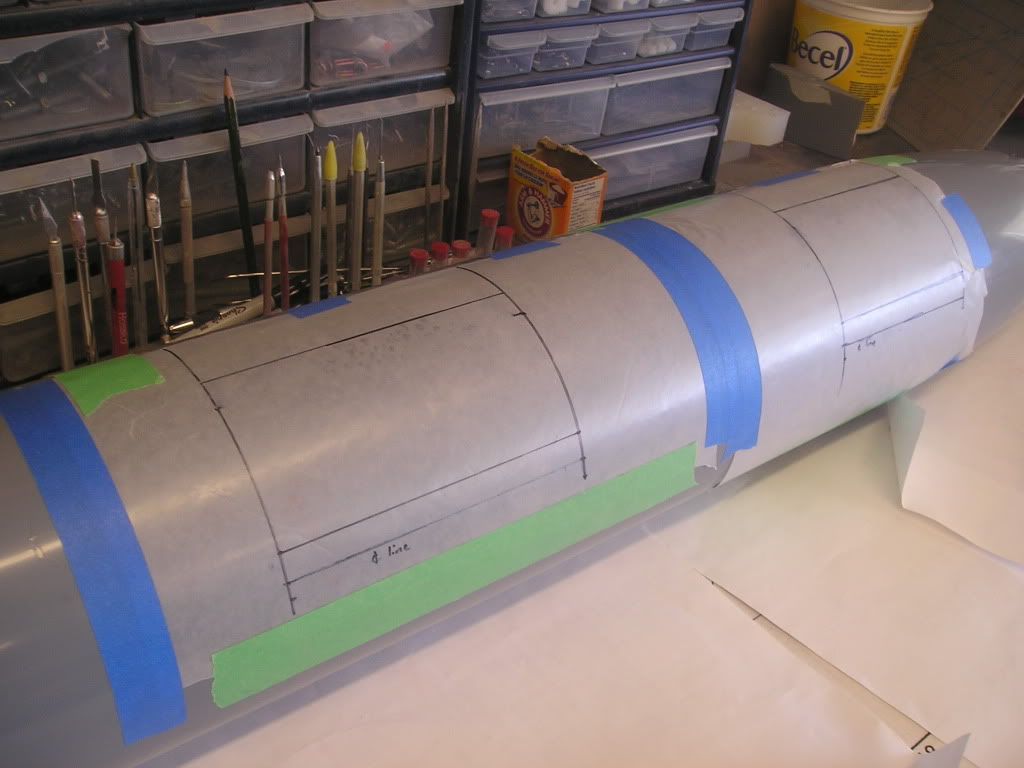
The shapes are all measured on my hull and the transferred to styrene. The aft blister took me the better part of an afternoon getting right as I only have two views of it; side view and bottom view, no front or rear. I’m thanking the model submarine gods that this piece ended up being symmetrical because making 2 would not be cool. Anyways, to get the shape right I traced the side profile shape onto some paper, folded it in half and cut it out like one of those paper snowflakes that we used to make in elementary school. I made the shape over sized and simply refolded the paper until it’s two most extreme points matched up to my hull markings. From there this shape was transferred over to some thin styrene.
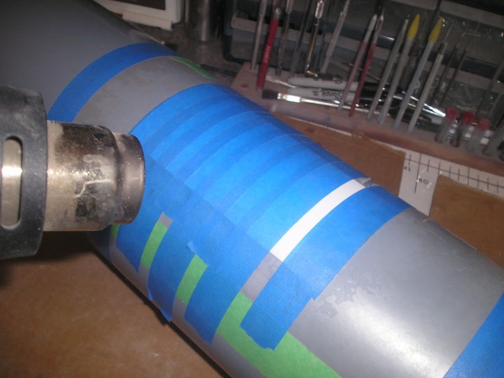
The shapes where taped into place where they would be fit to the hull, the exception here being the middle one as it fits on parallel hull surface. The entire surface of the shapes were covered in tape so that even heat from my heat gun would reach the styrene without causing any distortion> by applying the heat this made the styrene conform perfectly to the hull (well almost perfect anyway).
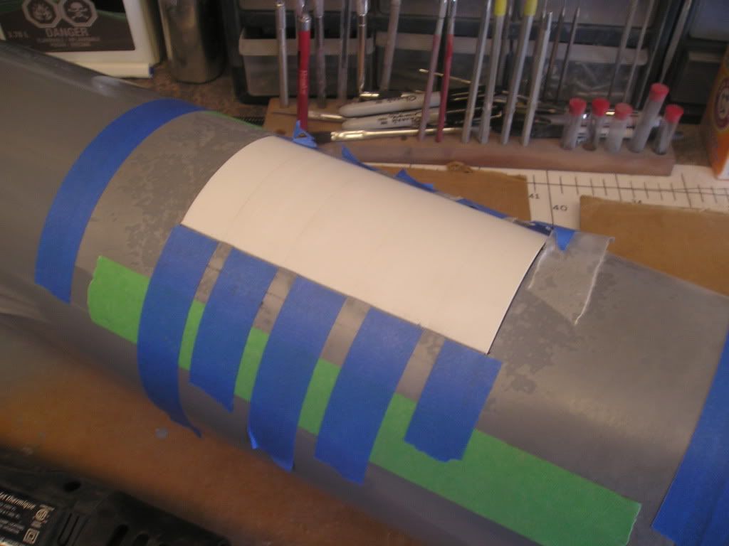
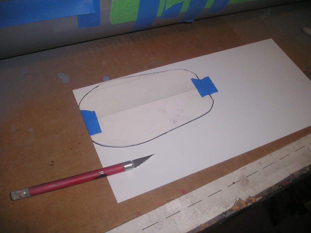
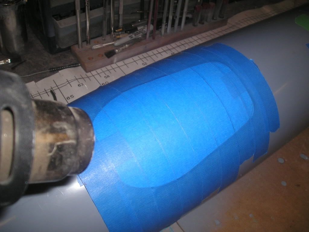
I do have information for front profile shapes of the front two blisters, so this shape was transferred over to cardboard, cut out and CA’d to the styrene.
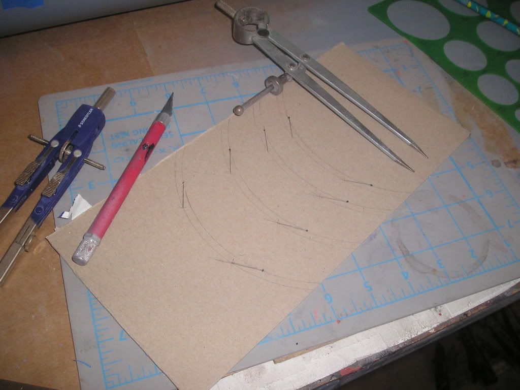
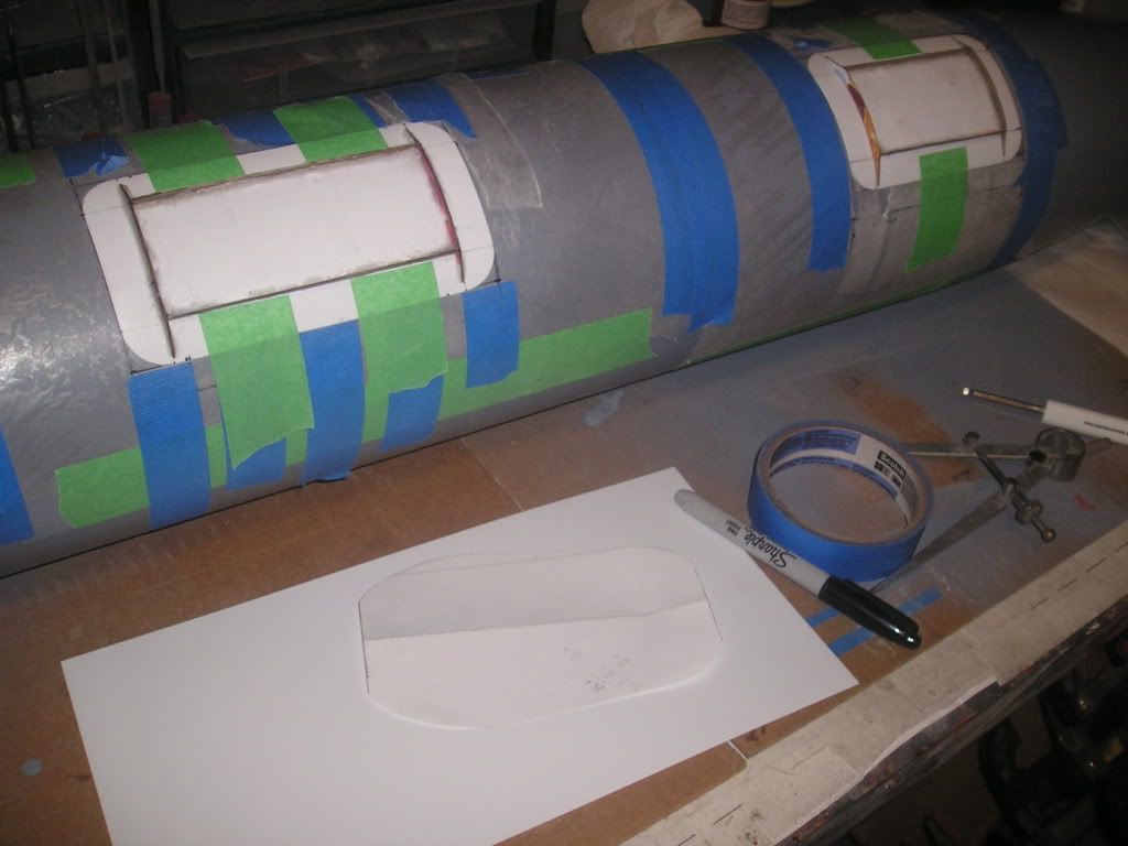
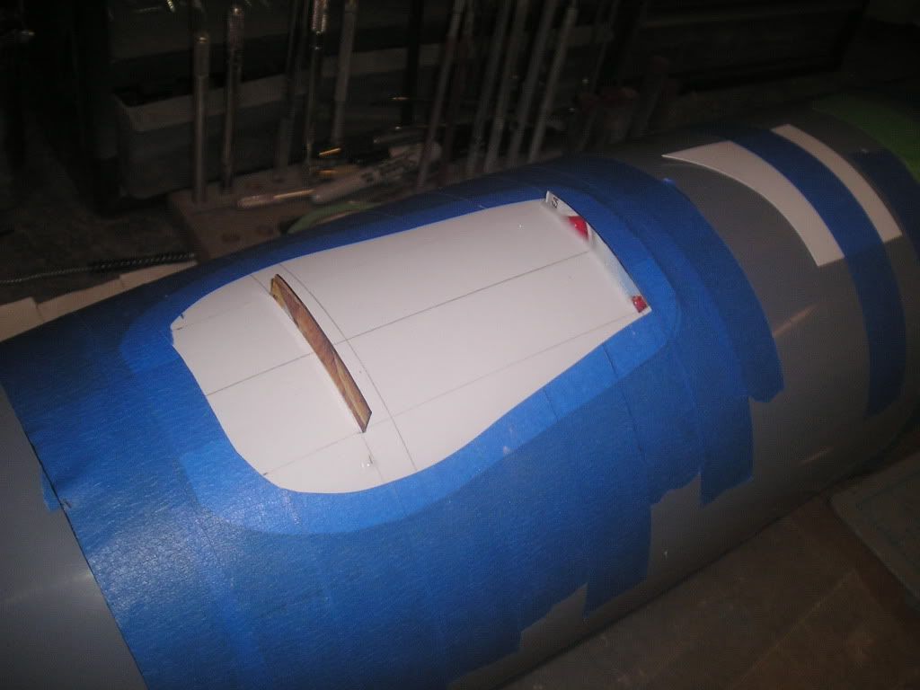
Leave a comment:
-
Tape dam filled with Bondo
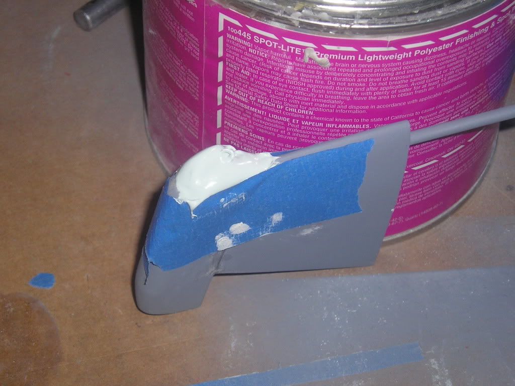
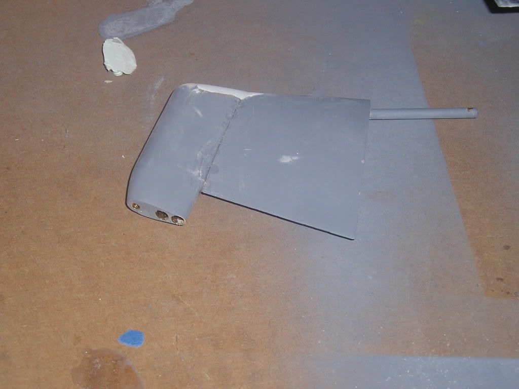
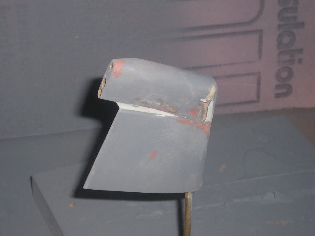
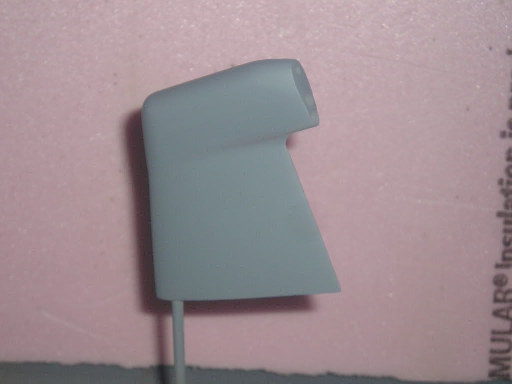
Finally a fillet is added to the front using the same technique used on my stern plane master
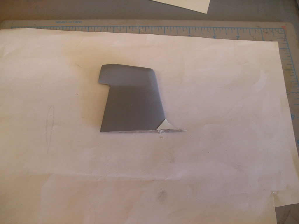
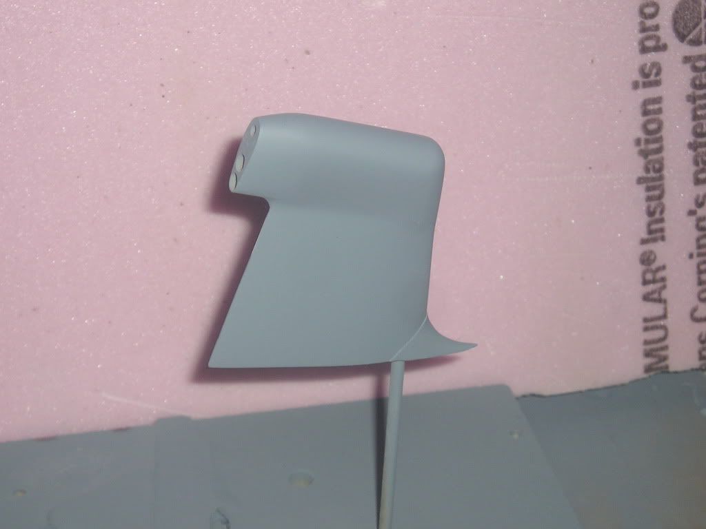
Regards,
JoelLeave a comment:
-
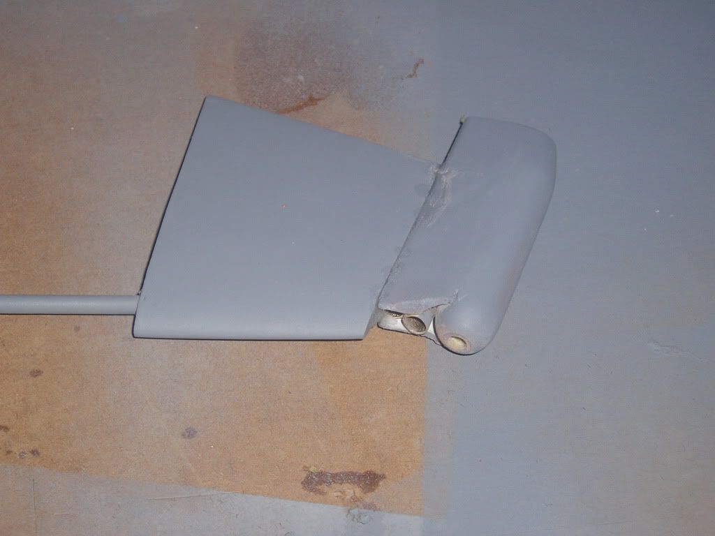
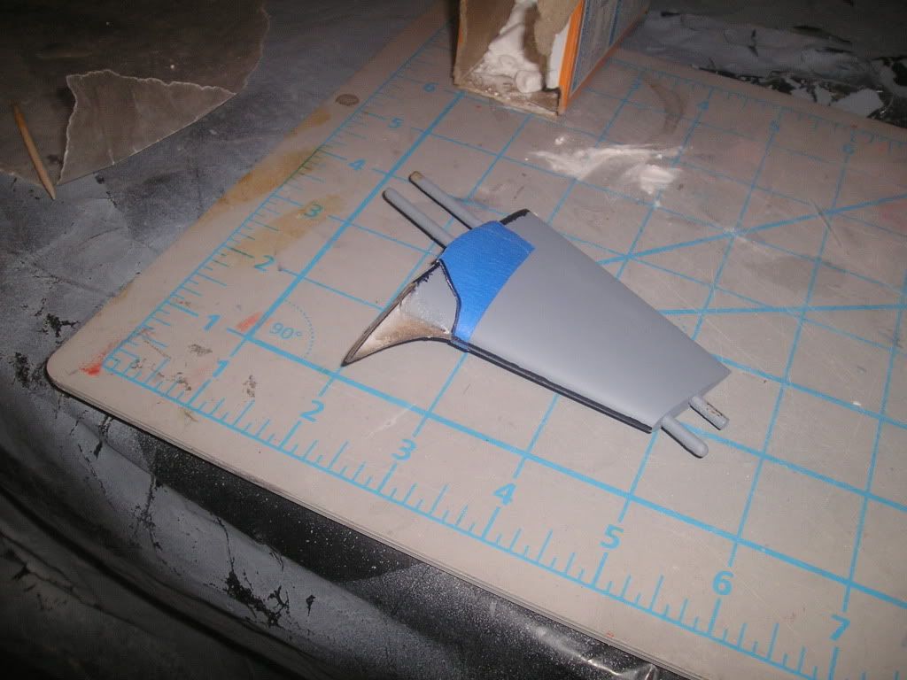
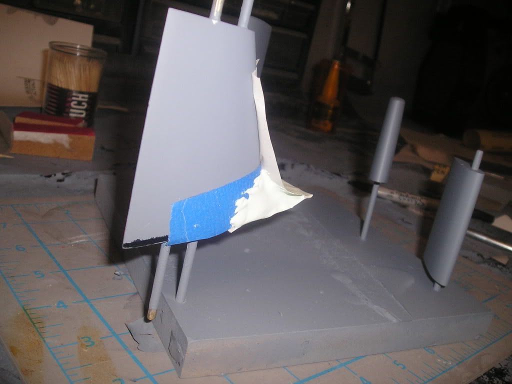
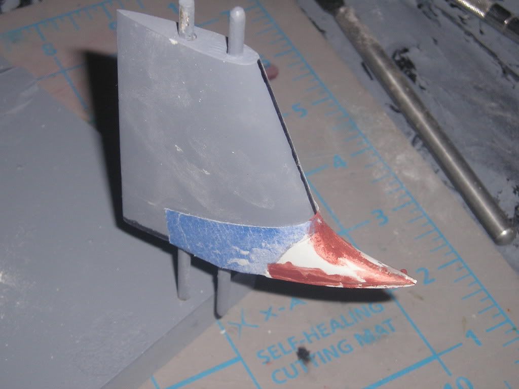
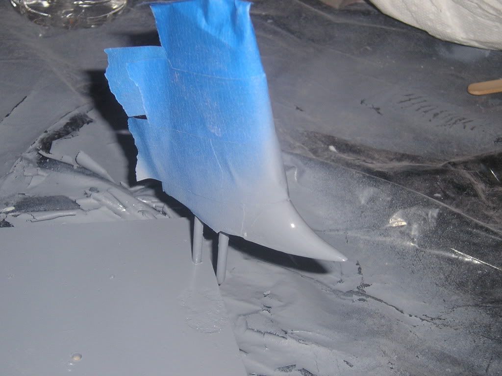
Now, on to one of the more challenging pieces I’ve taken upon myself to build; the dihedral fins. Not cut and dry respectively speaking like say, the rudders, we have many compound and complex curves in this baby. Starting from the hull, we have a “normal” shaped fin that blends into a tapering housing that ends in a bulbous pressure vessel-ish nozzle shape. This end assembly has 3 discharge points: fat line sonar, thin line sonar, and a third which comes off the blended nozzle of which I have absolutely no idea of which function it serves. But then that’s probably why I’m still alive, because I don’t have all the answers to the mysteries that this boat holds!
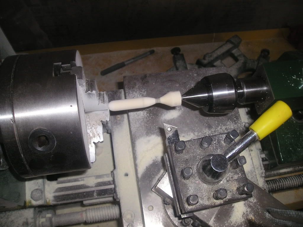
Starting with the nozzle, it is machined on my lathe and attached to 2 brass tubes using CA and baking soda.
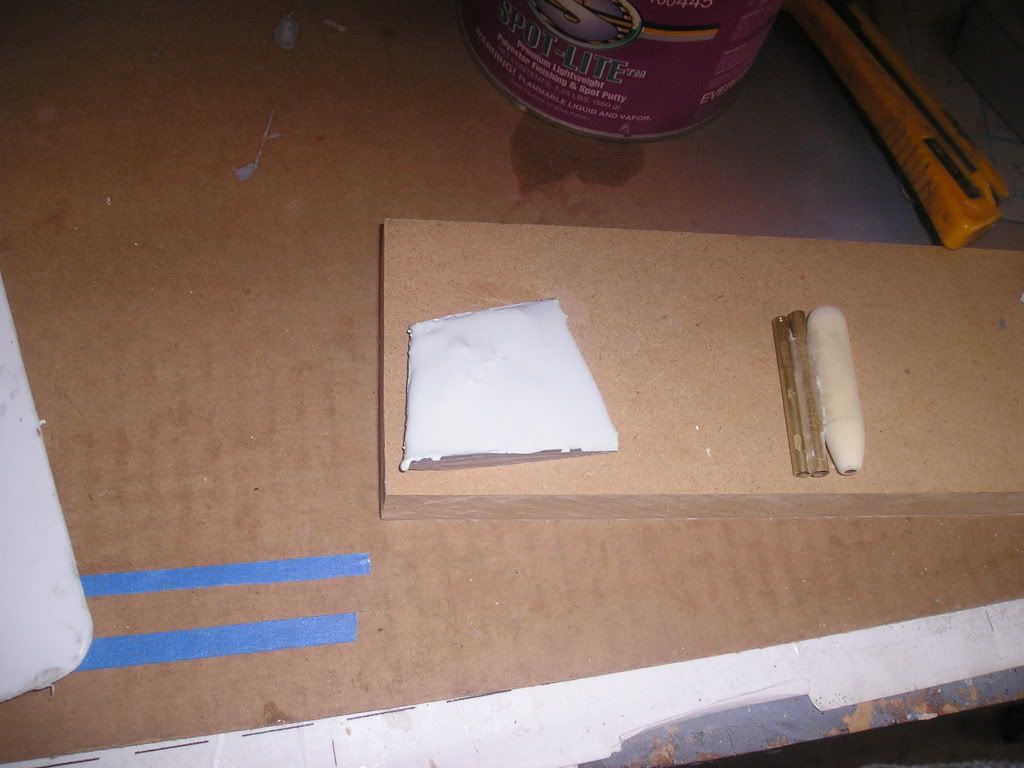
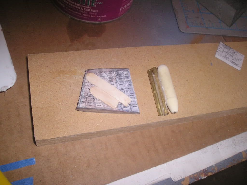
The same process is used for the regular part of the fin, except I’m using Bondo instead of foam. Much quicker and more solid, I just wait until the Bondo is half cured then follow the fin profile shapes with a sharp knife: a very smooth process!
CA solidified cardboard is used to finish the taper shape.
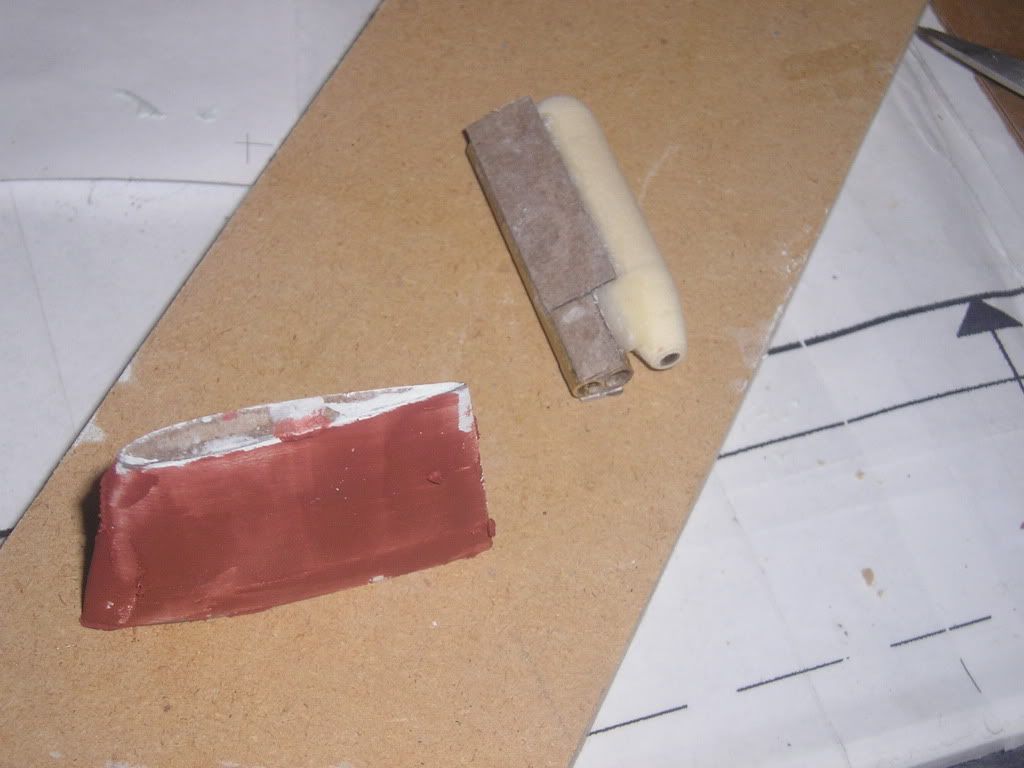
The parts glued together and in primer. There was lots of filling and flaw fixing here. I must have broken the taper off 4 times and re-glued it to get it right!
Leave a comment:
-
Lines showing where the plane parts will be split are lightly scribed into the part
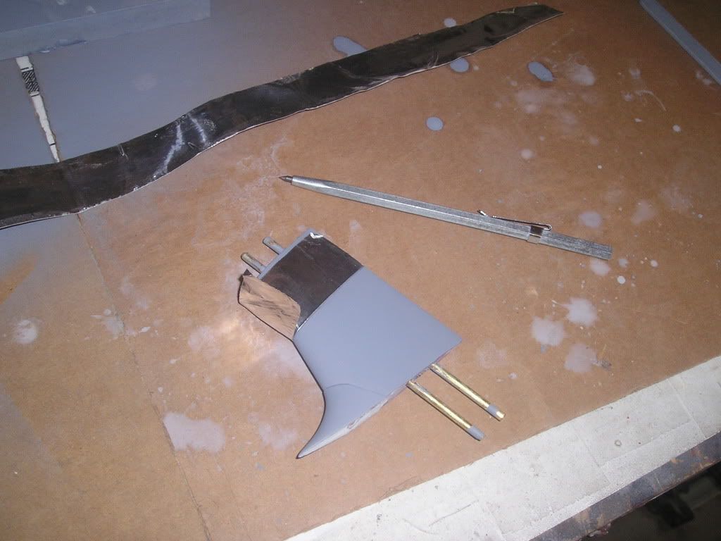
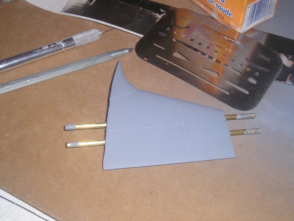
One piece moulds are used for these intermediate parts. This will allow for less flash and sprue removal and keep the reproductions faithful to the masters.

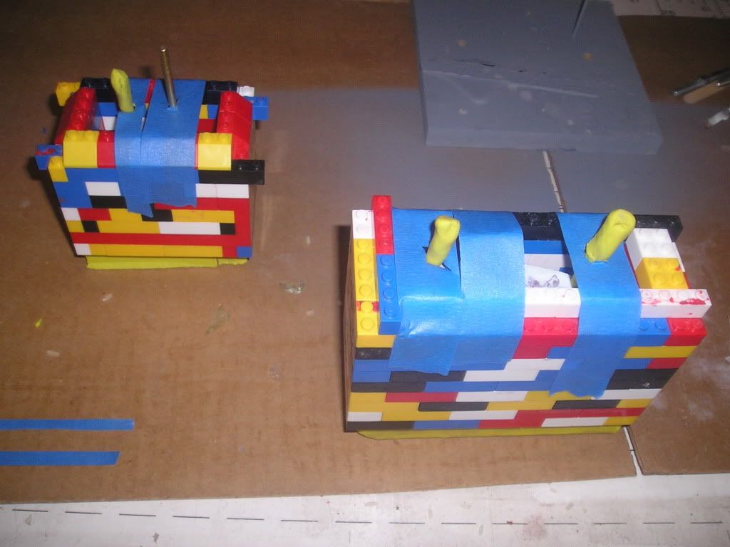
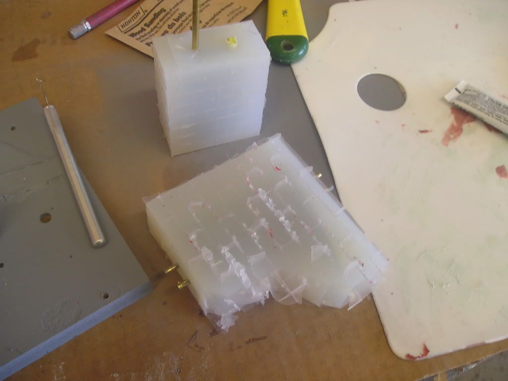
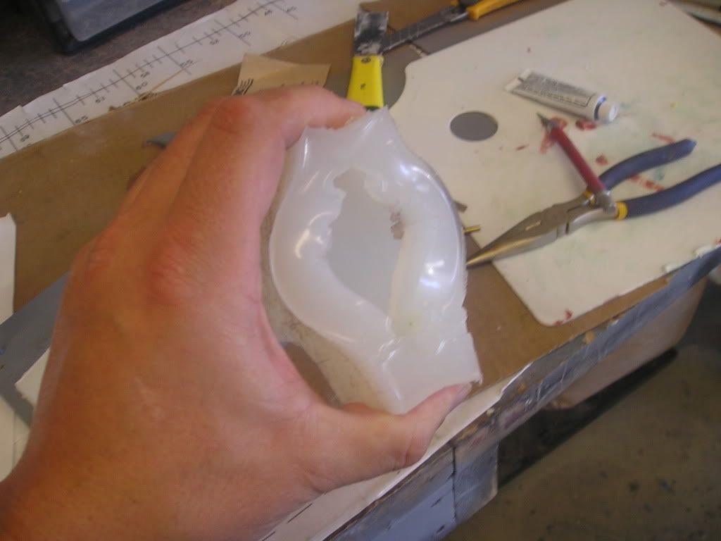
To get the part out, I simply blow compressed air into the bottom hole used to hold the centering shaft into place.
Tomorrow I’ll post my experience with the dihedral master!Leave a comment:



Leave a comment: