It is. I should finally have a little free time over the summer coming up
Joel
-
...and for us rc sub guys wanting to shoot them non-fly-by-wire Caswell torpedoes all straight-like and such, it's a really good thing. Not to mention not having to make complicated weirdo rotating torpedo shutters that are at a 10 degree angleLeave a comment:
-
Not necessarily to have them straight angled but the Brits have figured on straight for this boat. All modern US Nukes from the Thresher onwards had the tubes angled 10 degrees to accommodate the massive bow sonar. A modern warshot is not a dumb point and shoot weapon, meaning you don't need a straight line launch to target bearing.Leave a comment:
-
[QUOTE= Hey, at least they have straight-angle forward firing torpedoes...there has to be something said for that!
That would be a "good thing", right??
LOL
CGLeave a comment:
-
Surely there must be some sort of hydrodynamic advantage that comes with these funky designs? Hey, at least they have straight-angle forward firing torpedoes...there has to be something said for that!
JoelLeave a comment:
-
I find it interesting that the poms have always gone for a much different shape than the USN's teardrop hull design....but then they have always been a little odd!! Angled flight decks, steam catapults, Harrier jump jets...................................and stopid assed short sighted RN fleet cutbacks......
BruceLast edited by HvyCGN9; 04-01-2014, 06:19 AM.Leave a comment:
-
Amen to that!
A neat and organized work area is a sure sign of a sick minded wannabe!!!
Give 'er he**. Joel!!
CGLeave a comment:
-
... you learn a great deal about the Craft, and the man, by examination of the bench and work-space. Joel never ceases to amaze.
MLeave a comment:
-
I totally agree with you John. I kinda liken it to listening to a classic album...it doesn't catch right off the bat but takes numerous listens and then the genius starts popping out. This excludes all bonus tracks and engineering afterthoughts, of course lolLeave a comment:
-
Its looking mean Joel.
The Astute is the ultimate Gym junkie. Bulges evey where.
Nice workLeave a comment:
-
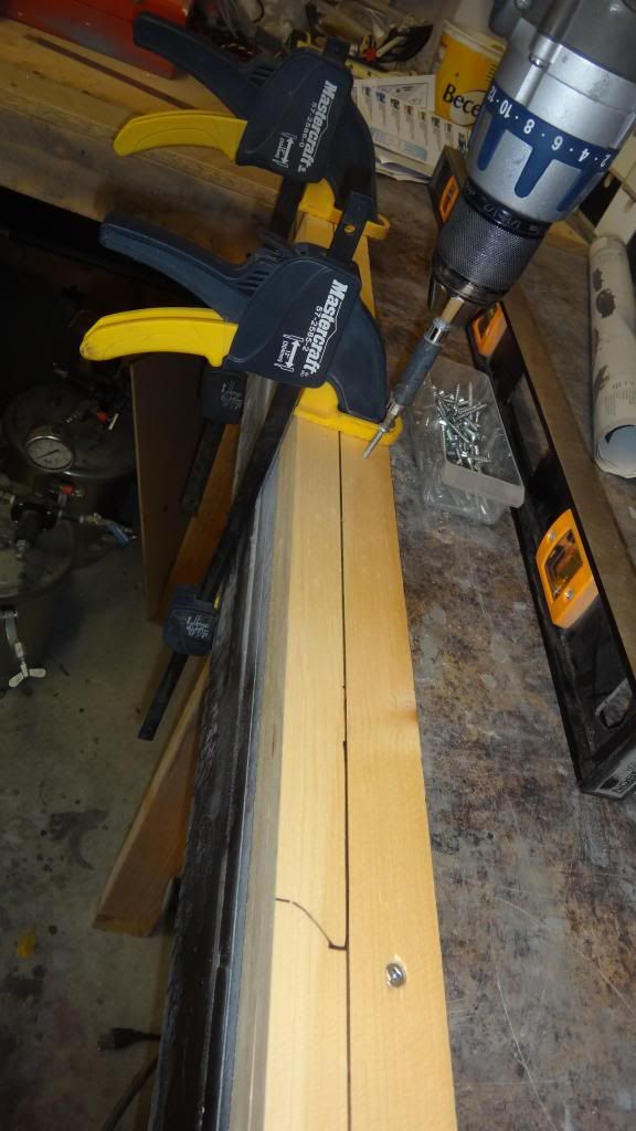
Next, I made an alignment jig that would allow me to install the bow on the center section. I cut up two straight lengths of wood, screwed them together, marked out the longitudinal center lines and drilled holes that would be used for attaching to the hull and for holding adjustment jack screws.
Once attached to the hull (I�m not worried about screw holes because the center portion of the hull gets a layer of tiles added on top of it later on) I brad nailed an end piece to the two lengths of wood. This was my total length stopper.
The bow was placed within the alignment compartment and the jack screws were tightened onto the center line of the bow section until it was held firmly. I was then able to adjust the screws in order to adjust my center line so that it lined up with the hull. The front of the bow was aligned so that its dead center met the dead center of the alignment jig.
When I was happy how everything looked, I taped up the gap between bow and center section and poured expanding urethane foam to fill the large gap and adhere the two parts together. The foam will be ground back past the filler level and the gaps will be filled with auto filler and then blended for seamless part fairing.
Leave a comment:
-
Chapter 9
We�re already on chapter 9 now and it doesn�t seem like much has been accomplished yet. Oh well, slow and steady and we�ll get this sucker built right.
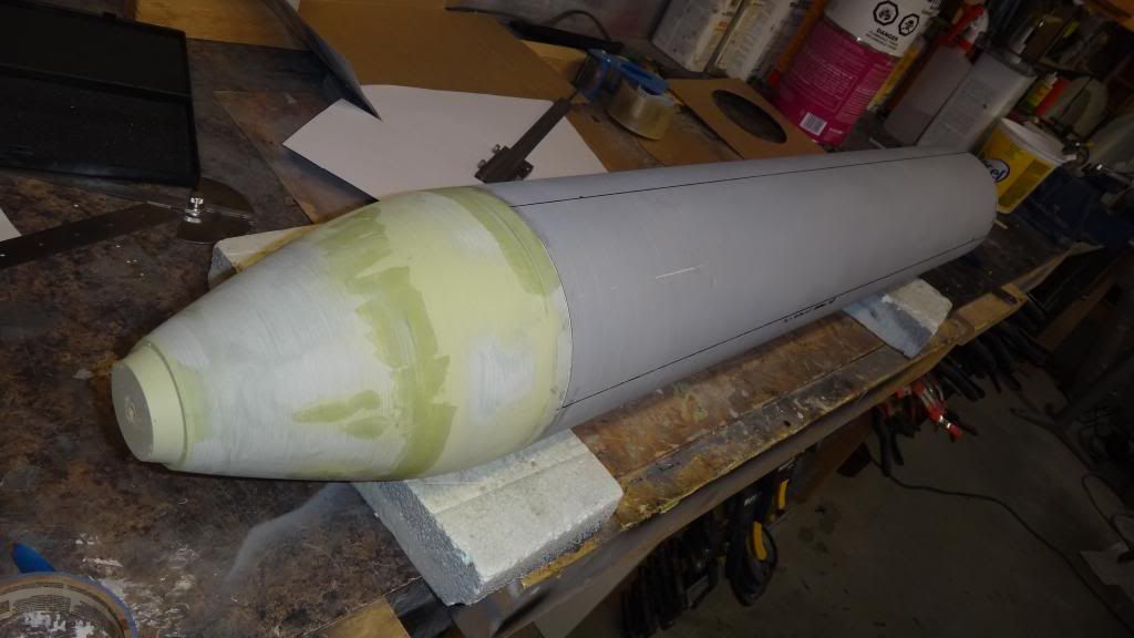
This time we put the hull sections together and give ourselves a basic foundation or canvas in which we can work some magic. The stern section isn�t really a big deal as I was able to machine flush surfaces on both stern and center sections for proper idiot proof mating. To hold these parts together I mixed some epoxy thickened with high density filler for good adhesion and let the parts cure.
Attaching the bow section to the center section was an entirely different and infinitely more complex process and this is because I wasn�t able to provide a machine-flush surface on the bow section due entirely to the nature of its shape. So, here is what I came up to counter the challenge:
First things first, I needed longitudinal reference marks depicting the top center, bottom centers, and port and starboard centers so this was done using paper wrapped around the hull and referenced at the top center reference line, the paper was removed and the length was divided into 4 sections. When wrapped around the hull again I could then mark out the reference quadrants. When done, the procedure was redone and checked mathematically just to ensure I had the accuracy I needed. There�s nothing worse than transferring details or trying to line up appendages to a model that has ****ed reference lines. How do I know this? Don�t ask please.
Leave a comment:
-
We’re already on chapter 9 now and it doesn’t seem like much has been accomplished yet. Oh well, slow and steady and we’ll get this sucker built right.
This time we put the hull sections together and give ourselves a basic foundation or canvas in which we can work some magic. The stern section isn’t really a big deal as I was able to machine flush surfaces on both stern and center sections for proper idiot proof mating. To hold these parts together I mixed some epoxy thickened with high density filler for good adhesion and let the parts cure.
Attaching the bow section to the center section was an entirely different and infinitely more complex process and this is because I wasn’t able to provide a machine-flush surface on the bow section due entirely to the nature of its shape. So, here is what I came up to counter the challenge:
First things first, I needed longitudinal reference marks depicting the top center, bottom centers, and port and starboard centers so this was done using paper wrapped around the hull and referenced at the top center reference line, the paper was removed and the length was divided into 4 sections. When wrapped around the hull again I could then mark out the reference quadrants. When done, the procedure was redone and checked mathematically just to ensure I had the accuracy I needed. There’s nothing worse than transferring details or trying to line up appendages to a model that has ****ed reference lines. How do I know this? Don’t ask please.
Leave a comment:


Leave a comment: