72 scale Lindberg IJN I53 with Kaiten Torpedoes

Collapse
X
 
  • Time
  • Show
Clear All
new posts

  • modelnut
    replied
    Yeah, "close" is relative. I have to decide how close I want to take this kit to the real I-53. As close as I can get without being too anal I guess.

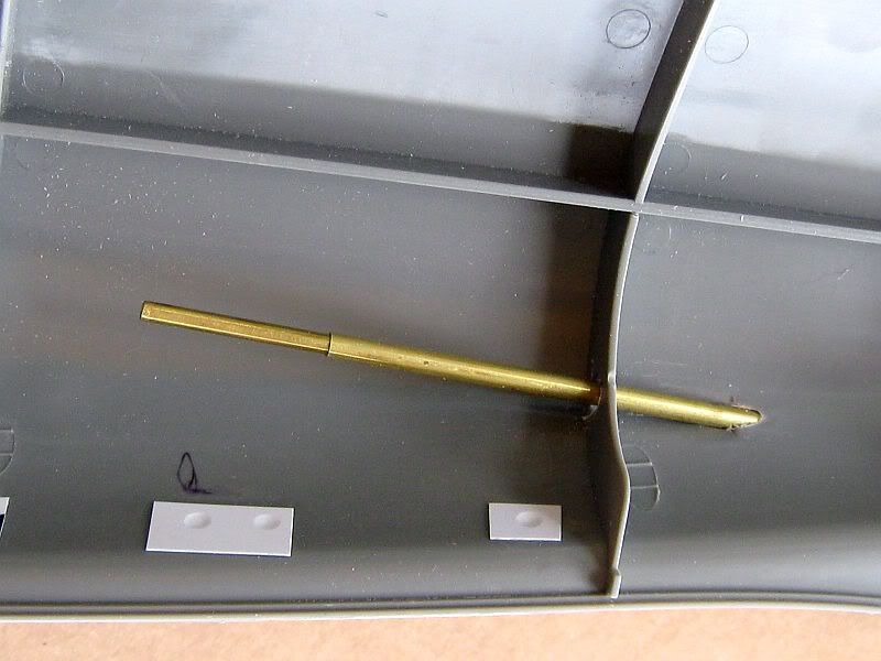
    I've replaced the kit propeller shafts with 1/8 inch K&S brass rods and tubes as Oztruck did.


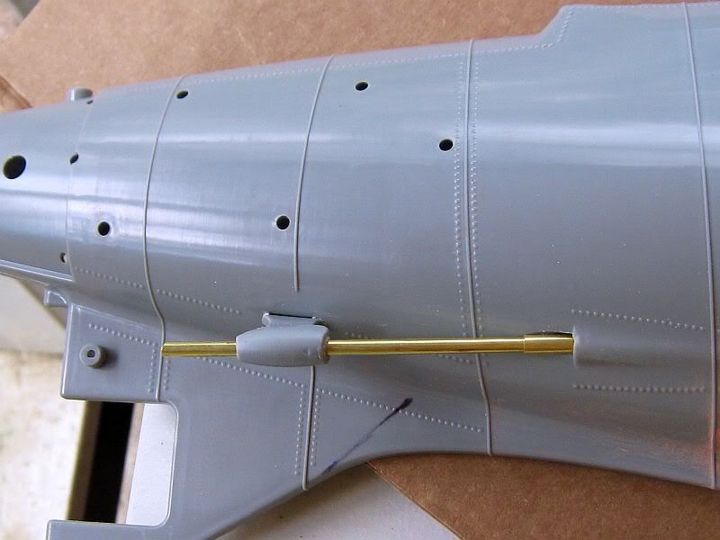
    I've left extra inside for the day I may take this kit RC. It isn't in the budget right now.


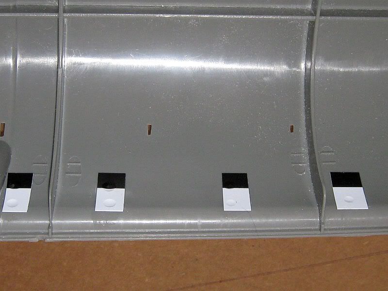
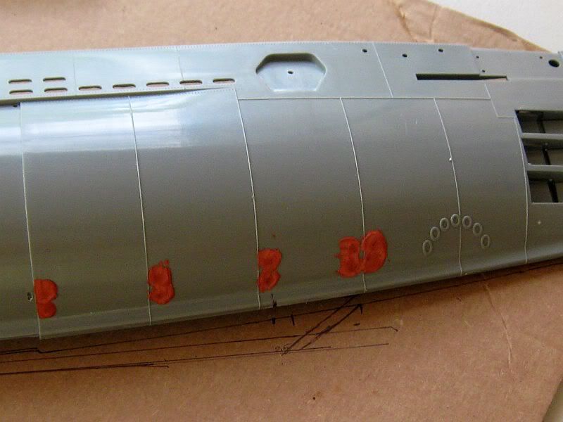
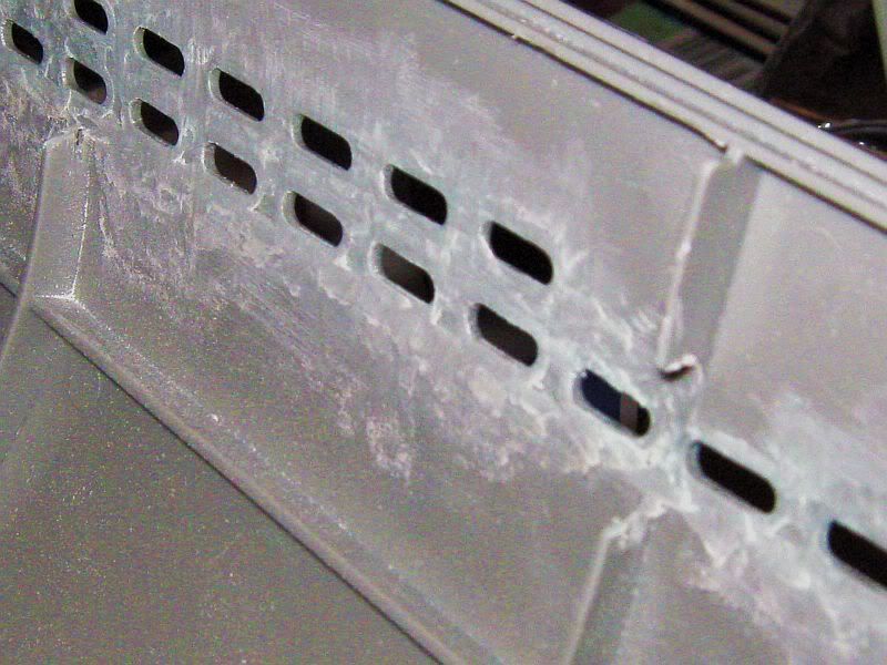
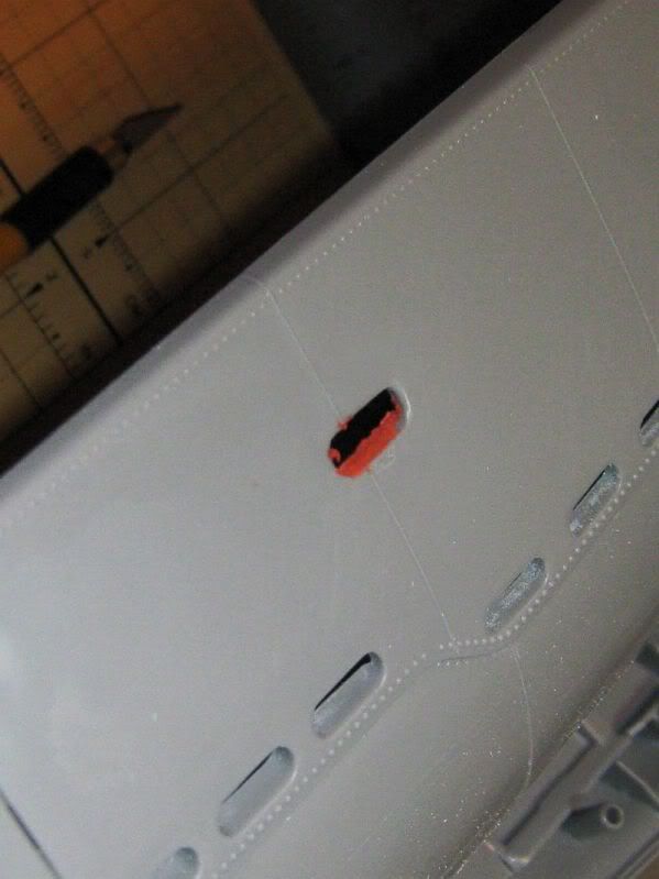
    Got disgusted with how inaccurate the kits details are especially concerning the weld lines and drain holes. So I backed each hole with plastic card from Walmart FOR SALE signs.


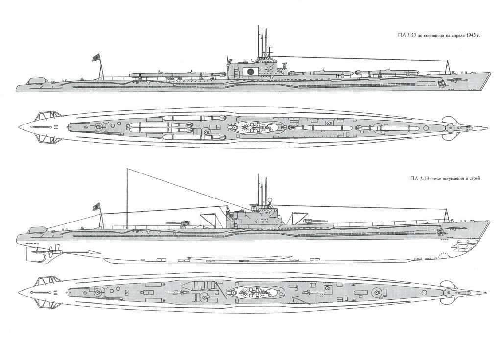
    Filled the other side with spot putty. And I'm starting to consider the keel. What the kit calls a keel isn't even close to the plans. So you can see a sketch here of the aft section.


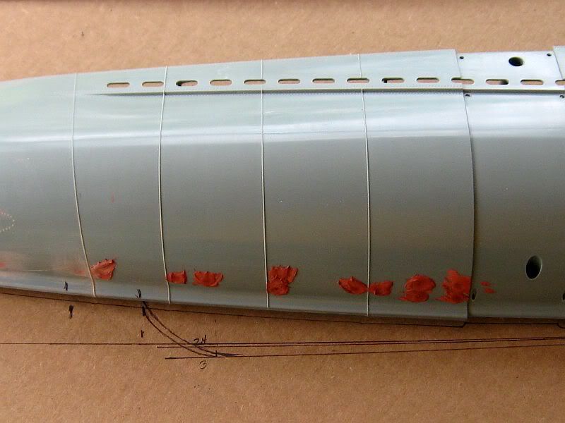
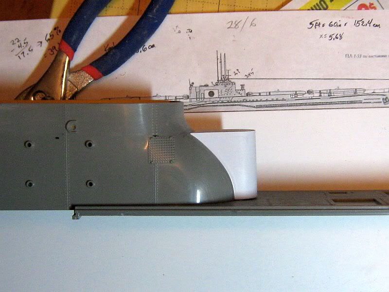
    Here is the forward. I don't know how far I will take this. One step at a time. I will keep you posted.


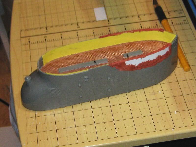
    I have the "front porch" almost finished.


    Here is a better look.


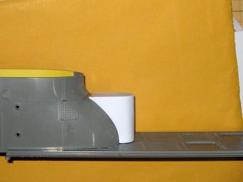
    Like I said, I have to make up my mind how close is close enough. But whatever I end up with will be better than what Lindberg had in the box.

    - Leelan

    Leave a comment:


  • He Who Shall Not Be Named
    replied
    Originally posted by modelnut
    Found an image of an IJN sub that more closely resembles Lindberg's tower configuration.

    [ATTACH=CONFIG]12777[/ATTACH]

    Wrong Kaitens on the deck though.

    - Leelan
    'Close' being a relative term.

    David

    Leave a comment:


  • modelnut
    replied


    Ground out the limber holes instead of just drilling.


    Only one "oops!" out of 272 holes. Beat the law of averages I'm sure.


    Just beginning to fix the conning tower using yellow FOR SALE signs from Walmart and some scrap plastic card. Still a long way to go.

    - Leelan

    Leave a comment:


  • modelnut
    replied
    Found an image of an IJN sub that more closely resembles Lindberg's tower configuration.

    Click image for larger version

Name:	ijn-i-58-submarine.jpg
Views:	1
Size:	17.3 KB
ID:	66790

    Wrong Kaitens on the deck though.

    - Leelan

    Leave a comment:


  • modelnut
    replied
    Thought about what I had read about the SNORT system and I think there is a detail of this model that plays into it --- the snorkel.

    Click image for larger version

Name:	Tower compare.jpg
Views:	1
Size:	62.5 KB
ID:	66778

    There is a lot of detail in the kit that doesn't work (duh.) But the basic shape and height of the snorkel is not too far off. I need to close that gap in the aft section just as Chris did. Then I plan to build that platform forward of the tower where there seems to be a big honkin' pair of binoculars.

    I think my skills will be equal to fixing a metal mesh inside the twin heads of the snorkel. Surely one of them would be the place to fix the business end of the SNORT.

    - Leelan
    Last edited by modelnut; 03-13-2012, 04:51 PM.

    Leave a comment:


  • modelnut
    replied
    OK. Didn't mess with rudder or planes. I worked graveyard the night before and I was a little out of it for the rest of the day. I opted to work on the conning tower instead. I chose to copy Chris's build and cut out the floor with my Dremel. I replaced the kit floor with a metal grill. Looks good. But not so different from Oztruck's work. No real point in posting pictures yet.

    I have a site where I can get brass propellers: http://www.shipsnthings.com/indexNS.htm The brass 3-blade D-type looks the closest to the kit parts.

    Code D
    (mm)
    D
    (inch)
    R/L Shaft
    (mm)
    P
    (mm)
    Max
    RPM
    156-03 35 1.40 R M4 35.9 10000
    156-04 35 1.40 L M4 35.9 10000
    156-05 40 1.60 R M4 41.0 8800
    156-06 40 1.60 L M4 41.0 8800

    Or can anyone here suggest something better?

    - Leelan
    Last edited by modelnut; 03-12-2012, 05:50 PM.

    Leave a comment:


  • modelnut
    replied
    Thanks!

    I will play around and see how much room there is to work with. The forward planes have to deal with the curve of the hull getting in the way. The aft planes and rudder might conflict if given too much freedom. I will find out today.

    - Leelan

    Leave a comment:


  • Subculture
    replied
    The 35 degree limit is similar to aeroplanes. Beyond that angle of attack, the control surfaces begin to stall, and can be less, rather than more effective.

    Boats with poor control surface area will require high angles of attack, boats with more generous areas may work well with considerably less. For instance I had a conflab with Dave about the Skipjack controls. I knew there was no way I would get 30-35 degree throw on either the rudder or dive planes without them clashing. Dave told me +/-10 degrees was enough for the rear planes.

    Leave a comment:


  • oztruck
    replied
    I have found it best to get as much movement as you can before any servos are connected. That equals no binding and room to adjust as needed. let the servo end limits be the deciding factor

    Cheers Chris

    Leave a comment:


  • modelnut
    replied
    OK. I have all 282 holes and vents open. Now I am about to tackle the planes and rudder. +/-45 degrees seems the logical limit of movement for these control surfaces. But I seem to recall someone (maybe HWSNBN) telling me years ago that +/-35 is the actual limit for practical subs.

    Which is it?

    - Leelan
    Last edited by modelnut; 03-08-2012, 07:02 PM.

    Leave a comment:


  • modelnut
    replied
    Originally posted by oztruck
    There is plenty of opportunity for work on this one, isn't there?

    Cheers Chris

    You said a mouth full!

    - Leelan

    Leave a comment:


  • oztruck
    replied
    I too looked through several plans, drawings and blue prints and could not verify that the front planes retracted, so i just have mine rotating, not retracting.

    You will have to make up new planes for the bow. Mine are just a little bit over sized to help with the submerged running and keeping periscope depth.

    There is plenty of opportunity for work on this one, isn't there?

    Cheers Chris

    Leave a comment:


  • modelnut
    replied
    Chris!

    What have you done with the forward planes? From these plans they don't look like they would fit in the hull but they look like they should.

    Do you have them rotating around horizontal and vertical axis?

    - Leelan

    Leave a comment:


  • modelnut
    replied
    OK. Not much to report just now. I've been too sick to work on the boat for much of the week. Feeling better now so I have been working on opening up the limber holes and flood/drain vents. After looking at many of the pictures on the sub pic thread I am feeling better about their size. But there are a hell of a lot of them. 78 limber and 58 f/d per side --- 272 in all.

    After looking over the research thoughtfully provided by Lt. Hermill:


    I think I will alter the conning tower and the bow to better fit the I-53 profile. Though there is a picture of the sail with the Japanese version of a snorkel on p35 of the Osprey book I haven't made up my mind about it. I've ordered an aftermarket AA gun so I will probably do just what Chris has done and leave off the snorkel. I don't know. That decision is a little way off right now.

    Enough of a breather I suppose. Back to cutting holes . . .

    - Leelan

    Leave a comment:


  • oztruck
    replied
    Leelan, they were painted black near the end of the war after they did some testing. Take your time with the bow and make it strong, you never know when it might run into something with it. Keep us posted on your progress.

    Cheers Chris

    Leave a comment:

Working...