Molch RC - 1:35

Collapse
X
 
  • Time
  • Show
Clear All
new posts
  • DrSchmidt
    Rear Admiral
    • Apr 2014
    • 1029

    Molch RC - 1:35

    After I did the side project "Molch" with interior and watching this guy's videos about making an RC version of the 1:350 scale I-400 (https://www.youtube.com/watch?v=c0qUOpaPLz8) I felt the temptation to make an RC version of the Molch. So I went to my digital drawing board....

    I plan to make it a static diver with actuated rudder and rear dive planes. The ballast tank main volume will be flooded and emptied like in the I-400 build via a u-shaped propulsor. The fine adjustments are going to be made via a servo actuated negative tank which will be based on a syringe. The propulsor and the drive motor will be 4 mm diameter drone motors that will be driven via controllers directly from the receiver power. The 4 battery cells will be located in the two torpedos. Everything will be located in a 3 cm WTC. As soon as I get the XXIII on the finishing line, I'll get on this project....we'll see. Click image for larger version

Name:	MolchRC-01.jpg
Views:	473
Size:	52.1 KB
ID:	168538

    Click image for larger version

Name:	MolchRC-02.jpg
Views:	455
Size:	67.6 KB
ID:	168539

  • DrSchmidt
    Rear Admiral
    • Apr 2014
    • 1029

    #2
    I finally found time to get this project started. First thing I wanted to get done is the battery storage in the two torpedos. I'll use 4 AA Nimh batteries that have about 14,2 mm outer diameter. At 1:35 scale a 533 mm torpedo has about 15,2 mm outer diameter. So the first task is to bring down the huge wall thickness of the kit's torpedos down to about 0,5 mm. For that I fabricated a draw blade out of the blade of a cutter knife. With that I started scraping out the inner of the torpedo halves. Regular checks against the desk light ensure even thickness distribution. All in all it was messy work . The drawing blade needed some fine tuning, but then it was a straight forward job, and I'm optimistic, that the result will work nicely.

    Click image for larger version

Name:	MolchRC-03.jpg
Views:	350
Size:	60.5 KB
ID:	178136

    Click image for larger version

Name:	MolchRC-04.jpg
Views:	345
Size:	43.4 KB
ID:	178137

    Click image for larger version

Name:	MolchRC-05.jpg
Views:	348
Size:	41.1 KB
ID:	178138

    Click image for larger version

Name:	MolchRC-06.jpg
Views:	340
Size:	40.7 KB
ID:	178139

    Click image for larger version

Name:	MolchRC-07.jpg
Views:	346
Size:	56.2 KB
ID:	178140

    Click image for larger version

Name:	MolchRC-08.jpg
Views:	344
Size:	43.0 KB
ID:	178141

    Click image for larger version

Name:	MolchRC-09.jpg
Views:	353
Size:	43.6 KB
ID:	178142

    Click image for larger version

Name:	MolchRC-10.jpg
Views:	347
Size:	42.0 KB
ID:	178143

    Then I started with the first test of the speed controllers and the motors for the drive propeller and the propulsor pump of the ballast system. I use tiny drone motors and speed controllers that are directly fed from the receiver. So the drive motors work analogous to standard servos which makes for a very easy wiring and it makes the need for a BEC or separate drive and receiver batteries obsolete. Just solder the motor wires to the controller, connect the speed controller to a servo tester, and voila: it works. Love it....

    Click image for larger version

Name:	MolchRC-11.jpg
Views:	342
Size:	37.2 KB
ID:	178144

    Click image for larger version

Name:	MolchRC-12.jpg
Views:	348
Size:	46.6 KB
ID:	178145


    Comment

    • MFR1964
      Detail Nut of the First Order
      • Sep 2010
      • 1315

      #3
      Nice work herr Doctor,

      Using those AA cells gives you weight, better usefull weight as lead, to seal those propulsion shafts there are little O rings present with a shaft diameter off 1 mm

      Manfred.
      I went underground

      Comment

      • DrSchmidt
        Rear Admiral
        • Apr 2014
        • 1029

        #4
        The Shafts are 0,7 mm. I have O-Rings, but I'll go for silicone. I've 3D-printed housings with space around the shaft base. That'll be filled with high-temp silicone. I'll give it a try and then test it.

        Comment

        • He Who Shall Not Be Named
          Moderator
          • Aug 2008
          • 12526

          #5
          Beautiful engineering and execution!! You got the batteries off-cylinder AND made use of their weight to stabilize the boat. I'm busy taking notes, pal! Love the scraper -- you're an old-school type of guy... I can tell.

          David
          Who is John Galt?

          Comment

          • DrSchmidt
            Rear Admiral
            • Apr 2014
            • 1029

            #6
            THanks folks....

            I've designed the u-shaped propulsor pump that will fill and empty the main ballast tank in CAD and printed it with my 3D printer. The drive motor is housed and suspended in the take-in tube. I've designed the outlet tube to have the same coss section as the intake tube (thus the neck at the transition). The big quetsion is: will the printed prop be stable enough. A test will show....


            Click image for larger version  Name:	MolchRC-14.jpg Views:	0 Size:	30.9 KB ID:	178187
            Attached Files
            Last edited by DrSchmidt; 02-12-2024, 03:52 AM.

            Comment

            • JHapprich
              Captain
              • Oct 2017
              • 740

              #7
              Hi, are those genuine micro esc's or converted servo electronics? In case, how did you override the poti's? I do not see a resistor.

              Comment

              • DrSchmidt
                Rear Admiral
                • Apr 2014
                • 1029

                #8
                Nothing modified....speed controllers as bought from ebay.

                Comment

                • DrSchmidt
                  Rear Admiral
                  • Apr 2014
                  • 1029

                  #9
                  I continued with the propulsor pump. The main thing I had to accomplish is getting the motor sealed watertight. The idea is to create a gasket by filling the red area with silicone.

                  Click image for larger version

Name:	MolchRC-15.jpg
Views:	311
Size:	62.8 KB
ID:	178289

                  Good idea that actually proved to be quite a challenge. The idea to use silicon originated from Youtube videos. They used standard air-drying silicone and that worked quite well. So I though I'd also give it a try, and I ailed three times. What went wrong? 1.) I also have no open surface to air, so the silicon doesn't cure, or better, it only cures at the hole for the motor shaft. 2.) Air-drying silicone shrinks, creating a tight grip around the shaft. So using standard silicone in my configuration didn't work. So I switched to 2-component silicone, usually used for making casting molds. Big advantage: It cures air-independently and it doesn't shrink. That way I git a working seal....well at least the motor turns. If it is water tight ... to be proven yet. The motor itself was secured with super glue gel.

                  Click image for larger version

Name:	MolchRC-16.jpg
Views:	309
Size:	54.4 KB
ID:	178290


                  Click image for larger version

Name:	MolchRC-17.jpg
Views:	307
Size:	41.0 KB
ID:	178291
                  Click image for larger version

Name:	MolchRC-18.jpg
Views:	308
Size:	46.9 KB
ID:	178292
                  The next step was to glue on the motor end cap using epoxy.

                  Click image for larger version

Name:	MolchRC-19.jpg
Views:	304
Size:	56.8 KB
ID:	178293

                  Comment

                  • DrSchmidt
                    Rear Admiral
                    • Apr 2014
                    • 1029

                    #10
                    From here on everything is pretty much straightforward, propeller on, end cylinder on and we have a pump.....tiny, but a pump:

                    Click image for larger version

Name:	MolchRC-20.jpg
Views:	286
Size:	28.4 KB
ID:	178312

                    Click image for larger version

Name:	MolchRC-21.jpg
Views:	286
Size:	33.7 KB
ID:	178313

                    Click image for larger version

Name:	MolchRC-22.jpg
Views:	288
Size:	42.9 KB
ID:	178314


                    Buidling a tiny propulsor pump for a ballst system for a 1/35 scale RC Molch

                    Comment

                    • DrSchmidt
                      Rear Admiral
                      • Apr 2014
                      • 1029

                      #11
                      The pump was finished by attaching the u-shaped siphon tube to the main body. The cable was routed out through a tiny hole that was then sealed using epoxy. The pump works quite well....happy with it.


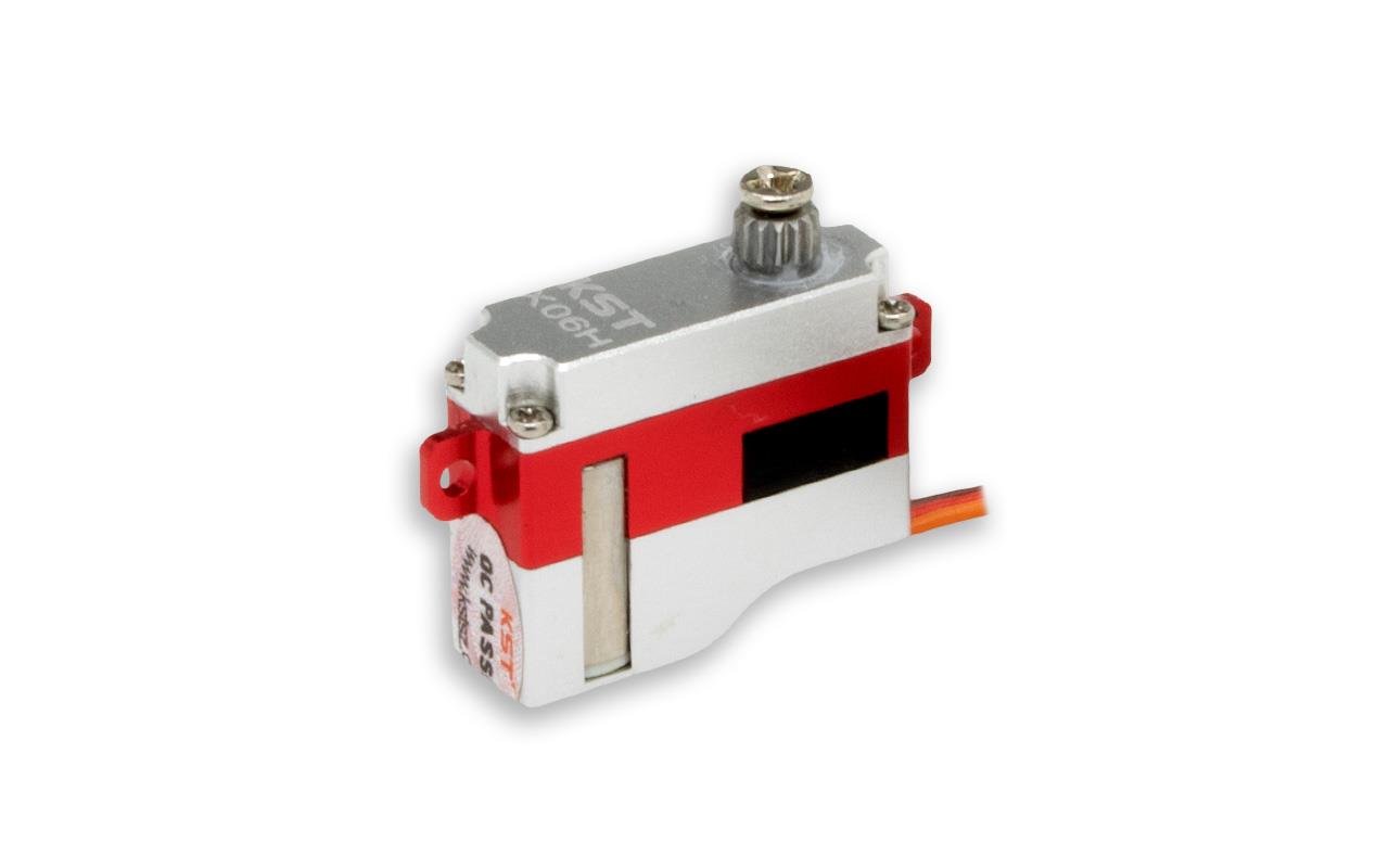
                      The next part of the ballast system is the negative tank, that is based on a syringe. The syringe body is cut to 30 mm length and was then glued into the servo support flange. On the other and a centering ring with three support feet was glued on the syringe tube using epoxy. All that will fit unto a 30 mm inner diameter wtc tube. The servo I'm going to use is a KTS X06H 7 mm servo. Tiny but extremely strong for its size.


                      Click image for larger version  Name:	MolchRC-25.jpg Views:	14 Size:	42.0 KB ID:	178374

                      Click image for larger version  Name:	MolchRC-26.jpg Views:	14 Size:	35.1 KB ID:	178375

                      Click image for larger version  Name:	MolchRC-27.jpg Views:	14 Size:	44.8 KB ID:	178376
                      Attached Files
                      Last edited by DrSchmidt; 02-23-2024, 05:41 AM.

                      Comment

                      • DrSchmidt
                        Rear Admiral
                        • Apr 2014
                        • 1029

                        #12
                        Continuing on the negative tank: The tiny servo is bolted down using 2 x M1,6 stainless screws. To limit the force that is put on the tiny aluminum brackets of the servo I printed small beams that have a tight fit against the back and front of the servo. That way, I have no bending of the brackets and lots of the force when actuating the syringe piston is directed into the servo chassis and not in fully into the tiny brackets.

                        Click image for larger version

Name:	MolchRC-28.jpg
Views:	267
Size:	47.2 KB
ID:	178444

                        Click image for larger version

Name:	MolchRC-29.jpg
Views:	243
Size:	50.3 KB
ID:	178445
                        Attached Files

                        Comment

                        • DrSchmidt
                          Rear Admiral
                          • Apr 2014
                          • 1029

                          #13
                          Ran into a problem....the piston of the syringe does not run easily enough to be moved by the servo (it pulls 1,5 kg), Too much friction. Any idea what to do about it? Thought about silicone spray.

                          Comment

                          • Subculture
                            Admiral
                            • Feb 2009
                            • 2170

                            #14
                            Syringes tend to be high in friction, perhaps to avoid air entering and causing an air embolism. You could machine a custom piston using a thin o-ring with a smaller amount of squish which will reduced friction, but if the servo cannot overcome the friction of the seal, it probably has no chance once the tank is installed and having to counter the air compression inside the wtc once retracted.

                            You could put the servo on a scotch yoke and use a full 180 degree motion which would double the torque, although you'd need a pulse extender. Another method would be to dismantle the servo and build the guts into a small screwjack, slower and less efficient but would hugely increase torque and self-locking against pressure. Or use a small geared motor with the servo amplifier as feedback.

                            Another possibility- use a small rubber diaphragm, cut out from some thin rubber sheet (marigold gloves) seen something similar done on small subs. Limited linear motion, plus the diaphragm can squish under pressure affecting trim.

                            Comment

                            • DrSchmidt
                              Rear Admiral
                              • Apr 2014
                              • 1029

                              #15
                              I'm basically trying to build the same thing like this guy here:


                              Contacted him....he says he uses silicone grease. So I'll give it a try.

                              Comment

                              Working...