
Rob,
Yes, she has a weight issue with that high tower, first thing i did was adding enough lead to counteract the weight of the tower, then started to play with the foam.
Chopped up the foam to get it all around the SD, you have the advantage of your waterline cut, i had to tinker with my beloved radial cut.
It will take some time to get her right, i ended up with a tad more lead to keep her upright with the tower, mine has more stuff inside, if i recall right it was about 450 gram of lead, you can use much less, i would try 100 gram more as the weight of your tower.
Manfred.
-
I just spotted Bob's build on U-Tube, he seems to use loads of ballast and foam!Leave a comment:
-
Mrs. Boattrainman was a bit pi**ed when her upstairs carpet got fried, have promised to be a good lad while my work space is in the house.
Anyway, here is the shot of the snort arrangement, the instructions state it should be mounted high in the tower.....
...............a small plastic mount topped by a magnet and another on the base of the snort.......
.................the fitting is pulled out the back of the second slot, again no bolts or screws..............
..............a final shot through the door that holds the rescue raft, the foam for the scope raising will be in front of it.
Now I can finalise the wiring from the nav lights, will take this through the front of the tower......
.............and down through the upper hull.......
...........I can fix the tower permanently in place now.
However, test tub trials have come up with an issue.
This is the first sub I've made that won't sit at the waterline without foam under the waterline, I think the large heavy sail on a small sub body is the issue.
So how does one get the balance right, just keep adding lead in the keel, then more foam around the waterline. And there's precious little room around the edge between the hull and the WTC.
The Boattrainman
Leave a comment:
-
When I was young, good-looking and stupid the first submarine I qualified aboard was a diesel-electric. So, battery charging -- the does and don't, and the evils of off-gassing during high charge/discharge rates -- has been ingrained in me.
So, on my toy submarines I always open up the battery compartment during the charge. ALWAYS!
Of the many, many Lithium-polymers I have been using the worst thing that ever happened was the occasional 'puffer' (not 'fluffer', you a-holes!), and even those continue to be used, even though their original capacity is long gone. The only Lithium-polymer fire I've had was the one I threw down onto the side-walk in front of my house. Never going to do that again!
DavidLast edited by He Who Shall Not Be Named; 06-01-2019, 09:04 AM.Leave a comment:
-
Good point David, and noted.
Just a bit nervous of boosting LIPOs while inside the sub, especially after one of my 5000mahs went on fire.
RobLeave a comment:
-
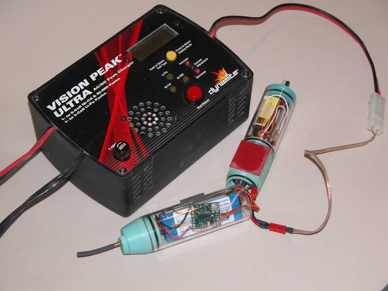
About charging the specific cells of a lithium-polymer battery: Not necessary on a model submarine -- you can get away with gang-charging all cells through the main wires coming off the power connector. We're not racing boats or high performance airplane drivers here; a less than ideal, maximum battery charge is a waste of effort. 80% capacity is good enough for us. I've been charging my r/c sub batteries this way for over a decade with no issues as to performance or noticeable damage to these batteries.
KISS!
DavidLeave a comment:
-
Hi Bob,
No real issue, we charge NIMHs in closed enclosures all the time (inside a Transmitter), but will open the WTC every now and then for maintenance.
Might be different with LIPOs.
Just got a pain in my butt having to strip the WTC down on my other subs to get at the balance plug on the LIPO for correct charging.
RobLast edited by The Boattrainman; 06-01-2019, 05:37 AM.Leave a comment:
-
No worries about charging batteries in a sealed container?-maybe vent the chamber when charging..Leave a comment:
-
I finished the wiring of the WTC and it was a challenge to say the least.
Up till now, I didn't get the fascination of micro subs, but after three weeks trying to fit it all in I kinda get it.
I made a new battery tray.......
........ I want to put 2 X 12V 2400mah rechargeable Nimh packs so the original had to go as it's for a 3700mah lipo.
The dry cells are for illustration only, waiting for the packs to arrive.
On the reverse side are the two 15amp Mtronic ESCs and the Futaba Receiver.......
......they just about fit, and are held with small styrene surrounds.
The only other thing I could squeeze in here was a switch for the ESC that feeds the receiver.....
.......a micro push button that sticks through the end plate and can be actuated by just removing the forward WTC cap.
And here is that cap.......
........I added bolts through the cap to solder tags so I can attach a charger, then I don't have to remove the batteries for charging. The red/brown cable will go to a plug taking power to the nav light in the tower.
The aerial is wrapped around the battery box inside the WTC.
And finally the motor and servo tray........
.......main switch with through hull push rod......
..........and an added 15amp fuse and the pitch controller on a custom made styrene mount over the pump motor.
Time consuming, more from trying to work out where it will all go and still ensure everything can be removed if broken.
The BoattrainmanLast edited by The Boattrainman; 05-31-2019, 02:00 PM.Leave a comment:
-
The WTC is a Ron Perrott item (R and R engineering), made especially for this sub and now available to all, includes drive motor, ballast pump, three servos, pushord magnetic connectors, and an On/Off switch and has approx. 450ml capacity, enough for this small sub.
Ron added an extra servo and outlet for the foreward dives planes for me.
The bulkheads for the 70mm WTC are made from 3.2mm styrene, and braced with Davids small triangular fittings he sent me.
The rear bulkhead has an adjustment fitting from 4mm stainless rod, the blue water inlet slots into this and holds the WTC in place.
.................you can just see it here, stops the WTC rotating, sliding backwards or rising at the rear.
At the other end the upper hull has small bulkhead that presses down on the WTC, stopping it rising at the front and a small bit of plastic on the front bulkhead to stop it sliding forward......
.......the WTC is held in place with no screws or fixings and can be simply lifted out from the magnetic connectors on the pushrods once the prop shaft coupler is undone.
At 615mm in length the WTC is a very tight fit but with a bit of trial and error I have it sorted.
The Boattrainman
Last edited by The Boattrainman; 05-19-2019, 12:46 PM.Leave a comment:
-
Nice work Rob,
It supports my opinion to add more details to make your boat stand out in the crowd.
I did made those antenna's retractable for the same reason you beefed them up, the flagpoles i can remove when needed.
As Tom stated, the rearlight is a nice trick, building historical correct is a matter of opinion, as long as you are satisfied with the result it's OK, unless you are building a specific number, but that is a completely other story.
And yes, compared to the price it's a nice detailed well fitting submarine, ready for adding some extra stuff.
Manfred.Leave a comment:
-
I found mine went together rather well. I would love to see them do another sub of this quality.Leave a comment:
-
Sure, all models are 'illusions', and I always think model railways are like 'plays', the front is the stage and the model trains the actors, backstage it's a diff story. Many UK exhibition layouts have copied theatre lighting and the proscenium arch, where the acion is confined to a defined space.
Have to say that for a few bucks this kit, and the tower in particular are superb to work with, the fit and finish is excellent, hat's off to Bronco (who seem to specialise in Military vehicles).
RobLeave a comment:
-
That is a cool solution for getting the light through. I often think of Hollywood when building details. If you visit a Hollywood set the front of a building may look real, but behind the building it is just framework. This is what you are doing. You are giving the illusion that the L bracket is where the wiring is coming from. I love it. It makes this sub your sub and that is awesome!Leave a comment:
-
Thanks buddy.
I've decided to make that rear light, even though it may be unique to one boat.
I used a 2mm round LED (usually used for model railway loco lighting) pushed out the rear of the tower, and embedded the resistor and wiring in epoxy.
The light housing is a 4mm plastic tube with a hole on both sides.
The LED is just visible from the rear, as it should.
I will fill in the sides with filler and hopefully the illusion will be that it hangs on the L bracket.
It's great to have something a bit different, there's a lot of model Type XXIIIs out there!
The Boattrainman
Leave a comment:
Leave a comment: