
Meine Herren,
Wie es scheint, ist ein U-Boot nicht genug für mich. Nun brauche ich etwas Hilfe. Auf den Vorschlag von Mr. Merriman hin habe ich mit der Arbeit am schönen 1/96 Klasse 212 begonnen. Er war so freundlich, mir einen teilweise gebauten Rumpf mit Kleinteilesatz zu überlassen. Ich beabsichtige, ihn als das aktuelle U-36 der Deutschen Bundesmarine zu bauen.
I'm sorry, I'm getting ahead of myself...
Gentlemen,
It would seem that one submarine was not enough for me. I am now beyond help. At the suggestion of Mr. Merriman, I have begun work on the beautiful 1/96 Type 212. He was kind enough to give me a partially started hull and fittings kit. My intent is to build her into the modern-day U-36 of the German Navy.
Credit where credit is due, I must thank our friend Jörg for helping with that translation. I took a bit of German back in high school, but my proficiency has faded as the years have gone by.
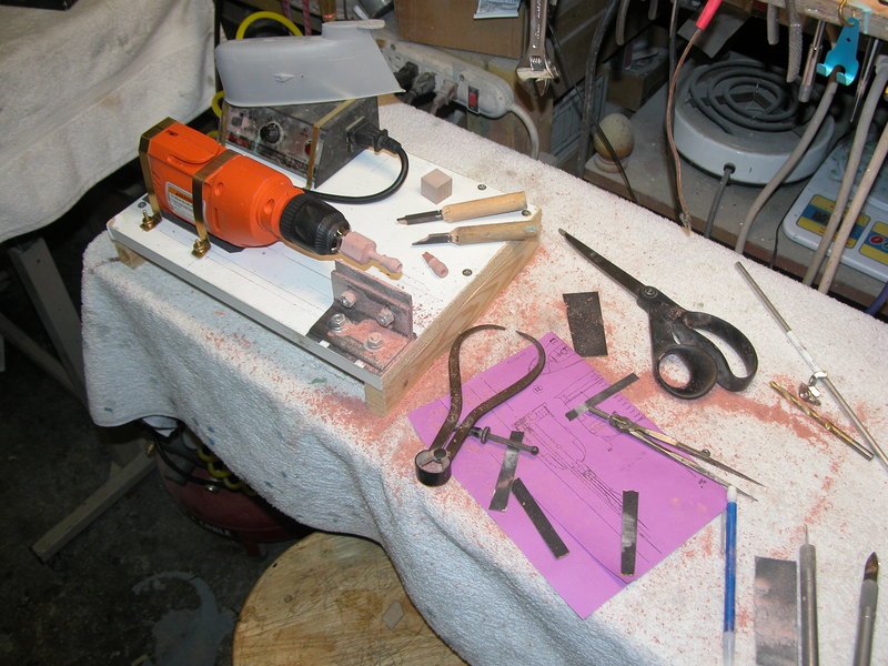
That said, I was lucky enough to come into possession of this lovely little boat when I visited David and Ellie last month. It really is a superbly engineered kit, and reading through its accompanying cabal report, it's clear that it was very thoughtfully designed to be as close to a shake & bake static-diving R/C scale model as you can produce. I say that with all due respect, of course. David made the task that much easier for me by giving me the mostly-completed hull and a fittings kit, so my task at this point is basically rigging it all up and finishing it. I had a good amount of free time this weekend as I was feeling under the weather, so I laid it all out on my dining room table and decided to see what kind of a mess I could make of things. Without further ado, I present to you U-36 (S186)
Starting with the already cut and joined hull pieces that David gave me. I promptly bottled the dust from his workshop and will be selling it as a good-luck potion for those interested. Kind of like those people who snort powdered Rhino horn for virility.
I'm trying to increase specific skill areas that are lacking with each new project, and it's no secret that I can't file a straight line worth a damn. Some people make it look easy, but in the past I've gotten all panicky and heavy handed about it. That said, the first thing I decided to do was to try and cut out the area for the aft navigation light on the sail. Of course, it went horribly awry. Taking inspiration from you bums, I remember reading something about it being easier to scribe detail into a softer medium than GRP or Styrene. Something like cured Evercoat metal glaze. I figured that filing probably worked the same way, so I gooped some into the gaping hole I made, sanded it to the profile of the sail, then cut and filed a new opening.

Relatively pleased with how that turned out, I then moved on to the sail planes. In the cabal report, it's mentioned that while you can make the sail planes functional on this boat, it's not absolutely necessary. For whatever reason, I decided to go with that and permanently mount them to the sail. I ended up getting two port side copies of the plane, and when you look closely, they have something of a glove that smooths out the transition from sail to plane. Since these aren't going to be functional, I cut the glove off of each piece, flipped one over, and voila!
I will come back to these with some Evercoat and properly blend them into the sail with a nice scribed line so they look as they should.
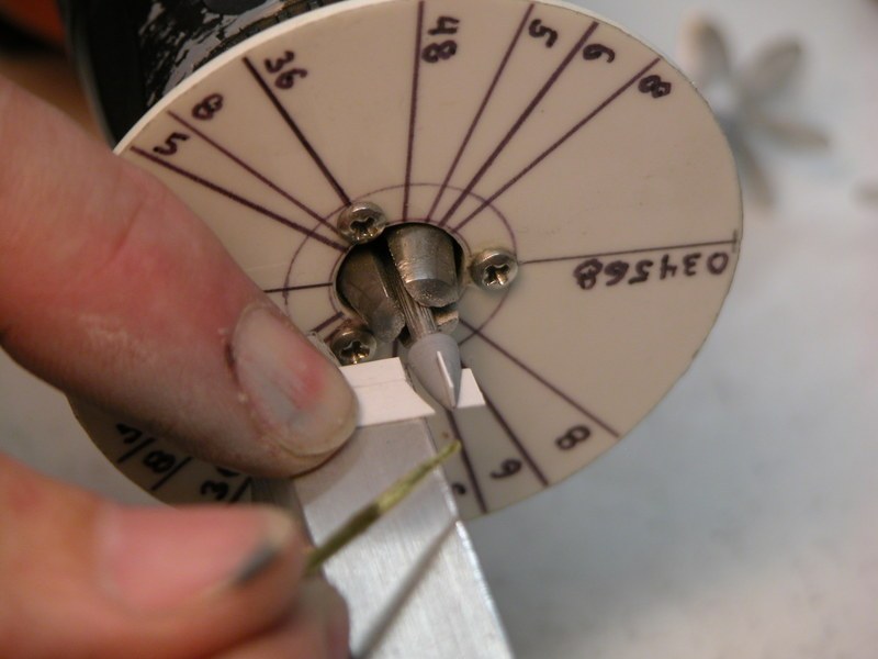
While playing around with the sail, I decided to open up a few holes on top for masts and periscopes.
I took a deep breath, steadied my trembling hands, and slowly... gently, began to file.
I smoothed-up the masts and installed the resin plug that they mount into. Initial test fitting showed promising results
Now, someone can correct me if I'm wrong here, but I'm about 90% sure that the specific mast that is in the aft spot should actually go in front of the flat-top one. However, I only got three from David, and I realized this after the fact. I may try to modify it to represent the proper mast. Maybe I'll file out the penetration in front and scratchbuild something to go in its place. Maybe I'll run for president and win in a landslide upset that no one saw coming. Who knows! But, I'm also a believer in sometimes not pushing one's luck.
While up on deck I got to thinking about ventilation. There were a lot of little pockets on CARTER where air bubbles would get trapped, and my method on that boat was to drill a 1/8" hole into the hull, and then cap it with a #2 metric flat washer. A bit of creative license, if you will, but it gets the job done and doesn't look that awful. I gave U-36 the same treatment, only I placed two quads of vents where the deck cleats would go. Again, I'm pretty happy with how it turned out, and with some paint and finish on it, I think they'll look just fine.
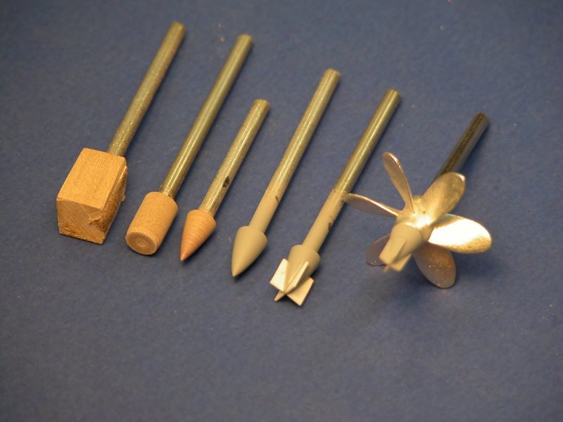
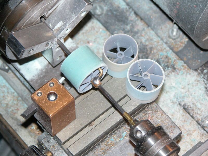
At this point, the weekend was beginning to draw to a close, but I thought I'd take a crack at the prop before calling it a day. As you can see, there was some flash to remove from the propellers
So, once more, absolutely terrified (but feeling a little emboldened by how things went on the sail) I carefully began to shape and file until

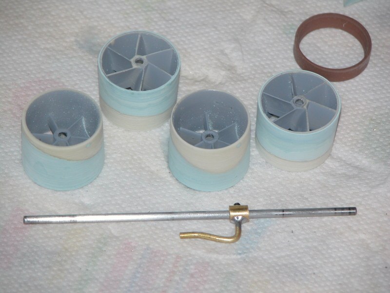
In David's report, he mentions pickling the in the white propeller with Ferric Chloride before priming and painting it. Well I didn't have any, but I was researching FC and ran across a number of examples of people making an etchant out of a 1.25 : 1.00 mixture of Vinegar and Hydrogen Peroxide with some salt mixed in. I mixed the ingredients, then added some baking soda and finally rinsed it off with 9+ PH water. Did it do anything? I haven't the slightest idea... but it was fun playing with chemistry, and I didn't ruin the prop. So there's that.
U-35 and U-36 both use the 7-blade skewback propeller as opposed to their four older sisters. Interestingly enough, U-35 and 36 seem to have been the victim of some unfortunate engineering squawks. To boot, U-35 was involved in an underwater collision that required her to be towed back to port for repairs to her rudder. Doing a bit of digging, it would appear that despite some meritorious action on the part of her crew, the WWII-era U-35 was also known as the bad luck boat of the 2nd U-Boot Flotilla after being involved in several accidents and collisions. Maybe there's a good reason why sailors are superstitious..... Not wanting to follow suit, but still wanting to use the pretty looking propeller, I opted to depict U-36. A few coats of primer and paint later, and
I'll take that. Now, the really cool thing about both U-35 and 36 is that they use what ThyssenKrupp Marine Systems refer to as the Propeller Boss Vortex Diffuser in place of the solid, conical shaped cap used on the earlier Type 212's.

....versus
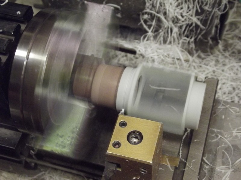
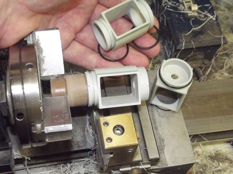
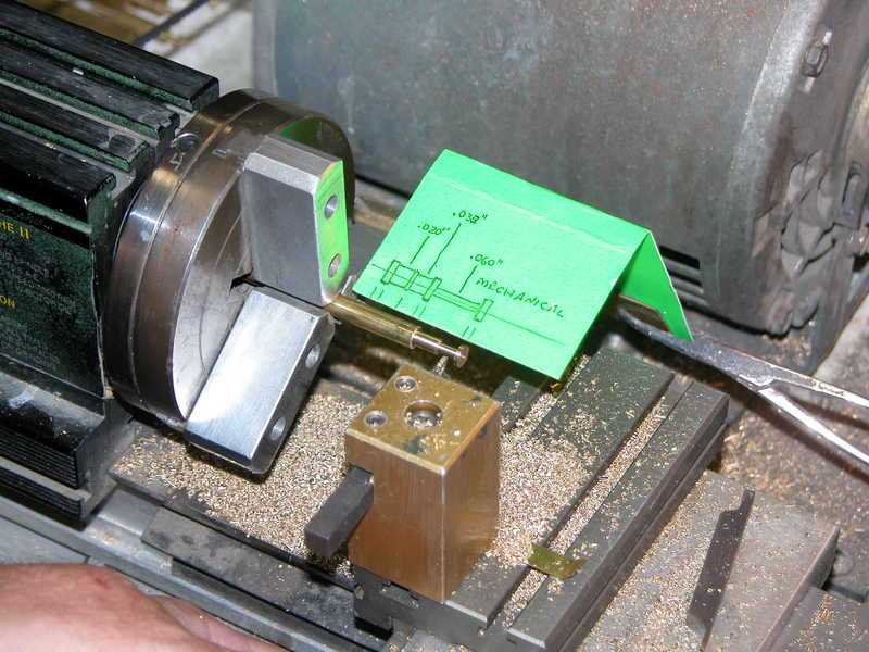
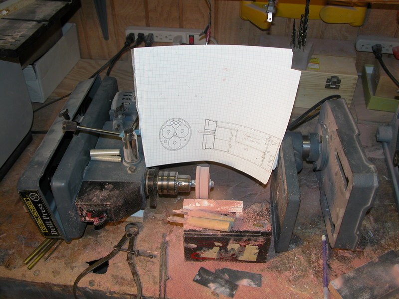
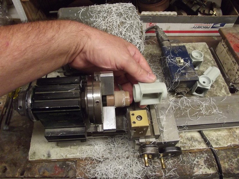
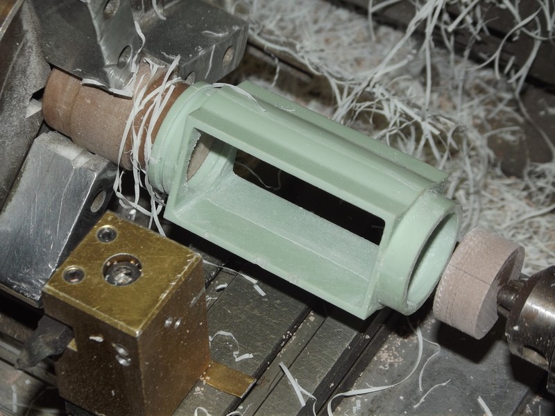
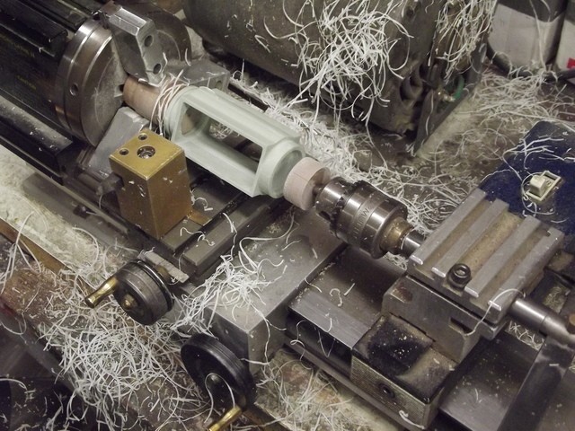
Well, I happen to have some bits of Renshape (also courtesy of Mr. Merriman) and I think that just looks too cool to not try and depict. Also, there's the question of scale accuracy. This part of the project, while small, will be completely uncharted territory for me. I have never worked with Renshape before, I have no idea how to create those spiral vanes on the body of the diffuser or the end-plate, and I suppose if we're carving in Renshape, we might as well cast the damn thing in resin as well. Another first for me.
SO! Here we are. It's Monday, and if you're still reading this novel at this point, I thank you for following along. There are still some miles to go, but I think U-36 is off to a good start. Most importantly, I'm having fun and learning new things along the way. Comments, critiques, and suggestions are always welcome. Until then, stay tuned.
Prost!
-Brady
Wie es scheint, ist ein U-Boot nicht genug für mich. Nun brauche ich etwas Hilfe. Auf den Vorschlag von Mr. Merriman hin habe ich mit der Arbeit am schönen 1/96 Klasse 212 begonnen. Er war so freundlich, mir einen teilweise gebauten Rumpf mit Kleinteilesatz zu überlassen. Ich beabsichtige, ihn als das aktuelle U-36 der Deutschen Bundesmarine zu bauen.
I'm sorry, I'm getting ahead of myself...
Gentlemen,
It would seem that one submarine was not enough for me. I am now beyond help. At the suggestion of Mr. Merriman, I have begun work on the beautiful 1/96 Type 212. He was kind enough to give me a partially started hull and fittings kit. My intent is to build her into the modern-day U-36 of the German Navy.
Credit where credit is due, I must thank our friend Jörg for helping with that translation. I took a bit of German back in high school, but my proficiency has faded as the years have gone by.
That said, I was lucky enough to come into possession of this lovely little boat when I visited David and Ellie last month. It really is a superbly engineered kit, and reading through its accompanying cabal report, it's clear that it was very thoughtfully designed to be as close to a shake & bake static-diving R/C scale model as you can produce. I say that with all due respect, of course. David made the task that much easier for me by giving me the mostly-completed hull and a fittings kit, so my task at this point is basically rigging it all up and finishing it. I had a good amount of free time this weekend as I was feeling under the weather, so I laid it all out on my dining room table and decided to see what kind of a mess I could make of things. Without further ado, I present to you U-36 (S186)
Starting with the already cut and joined hull pieces that David gave me. I promptly bottled the dust from his workshop and will be selling it as a good-luck potion for those interested. Kind of like those people who snort powdered Rhino horn for virility.
I'm trying to increase specific skill areas that are lacking with each new project, and it's no secret that I can't file a straight line worth a damn. Some people make it look easy, but in the past I've gotten all panicky and heavy handed about it. That said, the first thing I decided to do was to try and cut out the area for the aft navigation light on the sail. Of course, it went horribly awry. Taking inspiration from you bums, I remember reading something about it being easier to scribe detail into a softer medium than GRP or Styrene. Something like cured Evercoat metal glaze. I figured that filing probably worked the same way, so I gooped some into the gaping hole I made, sanded it to the profile of the sail, then cut and filed a new opening.
Relatively pleased with how that turned out, I then moved on to the sail planes. In the cabal report, it's mentioned that while you can make the sail planes functional on this boat, it's not absolutely necessary. For whatever reason, I decided to go with that and permanently mount them to the sail. I ended up getting two port side copies of the plane, and when you look closely, they have something of a glove that smooths out the transition from sail to plane. Since these aren't going to be functional, I cut the glove off of each piece, flipped one over, and voila!
I will come back to these with some Evercoat and properly blend them into the sail with a nice scribed line so they look as they should.
While playing around with the sail, I decided to open up a few holes on top for masts and periscopes.
I took a deep breath, steadied my trembling hands, and slowly... gently, began to file.
I smoothed-up the masts and installed the resin plug that they mount into. Initial test fitting showed promising results
Now, someone can correct me if I'm wrong here, but I'm about 90% sure that the specific mast that is in the aft spot should actually go in front of the flat-top one. However, I only got three from David, and I realized this after the fact. I may try to modify it to represent the proper mast. Maybe I'll file out the penetration in front and scratchbuild something to go in its place. Maybe I'll run for president and win in a landslide upset that no one saw coming. Who knows! But, I'm also a believer in sometimes not pushing one's luck.
While up on deck I got to thinking about ventilation. There were a lot of little pockets on CARTER where air bubbles would get trapped, and my method on that boat was to drill a 1/8" hole into the hull, and then cap it with a #2 metric flat washer. A bit of creative license, if you will, but it gets the job done and doesn't look that awful. I gave U-36 the same treatment, only I placed two quads of vents where the deck cleats would go. Again, I'm pretty happy with how it turned out, and with some paint and finish on it, I think they'll look just fine.
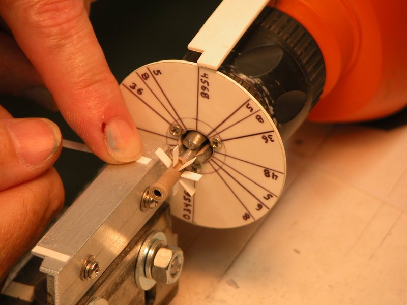
At this point, the weekend was beginning to draw to a close, but I thought I'd take a crack at the prop before calling it a day. As you can see, there was some flash to remove from the propellers
So, once more, absolutely terrified (but feeling a little emboldened by how things went on the sail) I carefully began to shape and file until
In David's report, he mentions pickling the in the white propeller with Ferric Chloride before priming and painting it. Well I didn't have any, but I was researching FC and ran across a number of examples of people making an etchant out of a 1.25 : 1.00 mixture of Vinegar and Hydrogen Peroxide with some salt mixed in. I mixed the ingredients, then added some baking soda and finally rinsed it off with 9+ PH water. Did it do anything? I haven't the slightest idea... but it was fun playing with chemistry, and I didn't ruin the prop. So there's that.
U-35 and U-36 both use the 7-blade skewback propeller as opposed to their four older sisters. Interestingly enough, U-35 and 36 seem to have been the victim of some unfortunate engineering squawks. To boot, U-35 was involved in an underwater collision that required her to be towed back to port for repairs to her rudder. Doing a bit of digging, it would appear that despite some meritorious action on the part of her crew, the WWII-era U-35 was also known as the bad luck boat of the 2nd U-Boot Flotilla after being involved in several accidents and collisions. Maybe there's a good reason why sailors are superstitious..... Not wanting to follow suit, but still wanting to use the pretty looking propeller, I opted to depict U-36. A few coats of primer and paint later, and
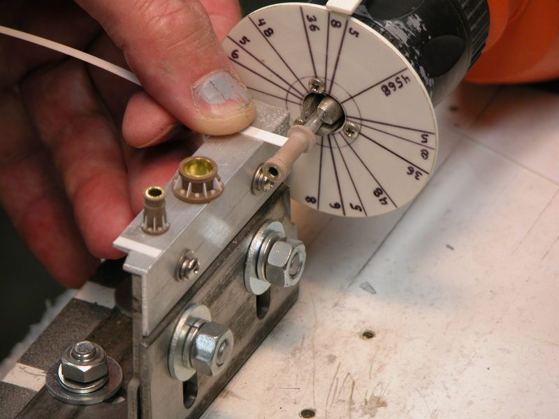
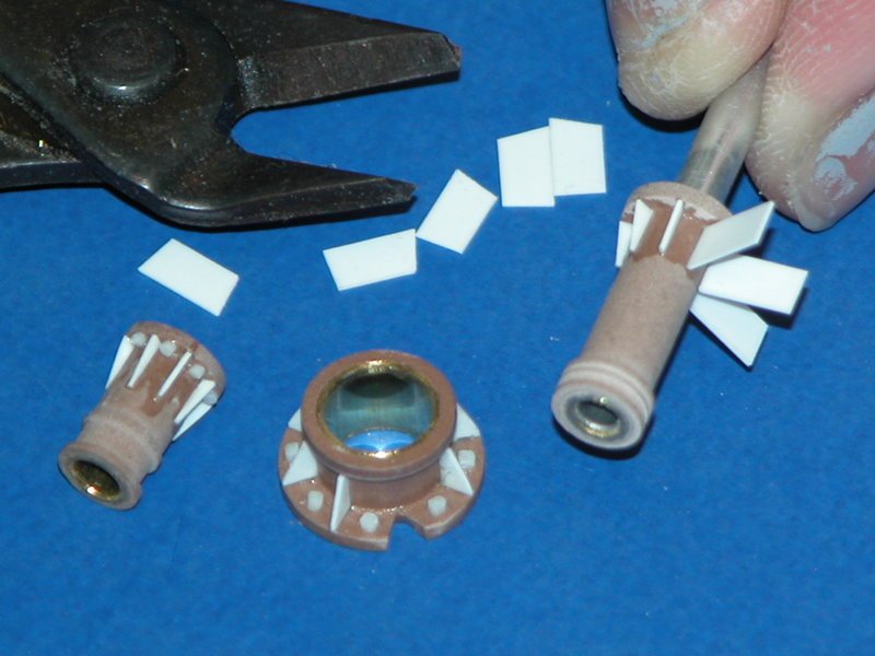
I'll take that. Now, the really cool thing about both U-35 and 36 is that they use what ThyssenKrupp Marine Systems refer to as the Propeller Boss Vortex Diffuser in place of the solid, conical shaped cap used on the earlier Type 212's.
....versus
Well, I happen to have some bits of Renshape (also courtesy of Mr. Merriman) and I think that just looks too cool to not try and depict. Also, there's the question of scale accuracy. This part of the project, while small, will be completely uncharted territory for me. I have never worked with Renshape before, I have no idea how to create those spiral vanes on the body of the diffuser or the end-plate, and I suppose if we're carving in Renshape, we might as well cast the damn thing in resin as well. Another first for me.
SO! Here we are. It's Monday, and if you're still reading this novel at this point, I thank you for following along. There are still some miles to go, but I think U-36 is off to a good start. Most importantly, I'm having fun and learning new things along the way. Comments, critiques, and suggestions are always welcome. Until then, stay tuned.
Prost!
-Brady


Comment