Welcome to our forums. For the best in R/C submarine kits, components and accessories, be sure to visit the Nautilus Drydocks
If this is your first visit, be sure to
check out the FAQ by clicking the
link above. You may have to register
before you can post: click the register link above to proceed. To start viewing messages,
select the forum that you want to visit from the selection below.
At 1/96 scale the bridge windows � more correctly described as, �deadlights� � on submarines are worth the effort and time required to make them transparent, or at least as transparent as can be reasonably expected.
You can go with vacuformed inserts, or a slug of clear solid acrylic, but in this case I went with the David Manley method of making the deadlights from clear epoxy adhesive. I�ve had moderate success achieving what I would call �acceptable� transparency, but this being my third submarine model to feature these type deadlights, I�m still zeroing in on what to do, as well as what not to do, when employing this technique. Hopefully the big 1/96 SIERRA-2 deadlights will see an improvement over this and previous work.
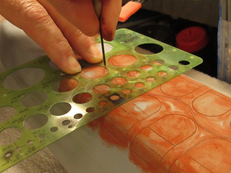
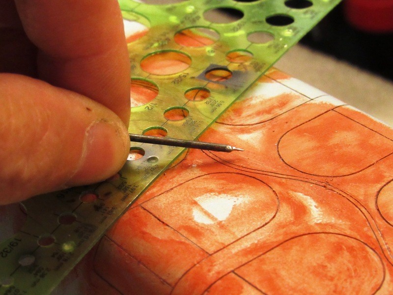
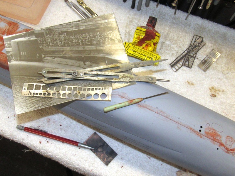
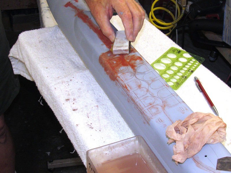
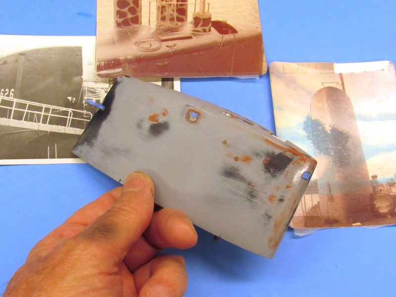
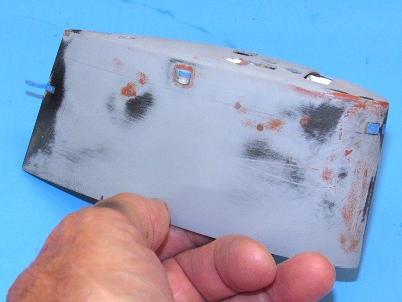
First task was to identify where the deadlights would go at the upper leading edge of the sail, mark their outlines with pencil � a bit bigger than they will eventually be � and cut open the three opening, �frames� if you will, that would be back-filled with clear epoxy glue. Note just some of the reference photos used to guide me as I opened up the deadlight frames. The job entailed not only grinding the three openings, but also grinding away excess laminating resin from within the sail. It would not do to have clear deadlights only to let them reveal a way out of scale thickness to the deadlight framing.
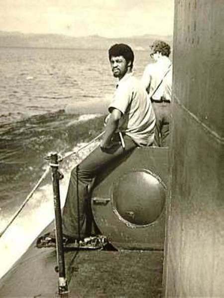
(The color photo is our stop-over at Oahu before completing our transit to New London for Poseidon conversion. My ninth and last patrol on the Pig-Fish. Spent the rest of my career in the diving community; ships husbandry, salvage, security swims, training, and chasing Filipino gal�s around bar-stools).
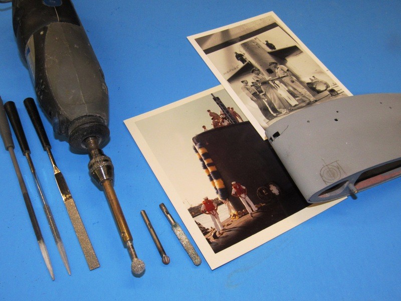
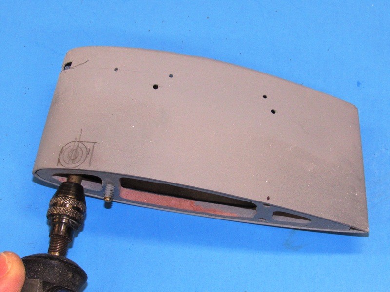
I�ve developed shank-extensions for my Dremel moto-tools. The objective of that accessory is to increase the reach of a rotary tool much farther from the chuck than the typical tools shank length of two-inches will permit.
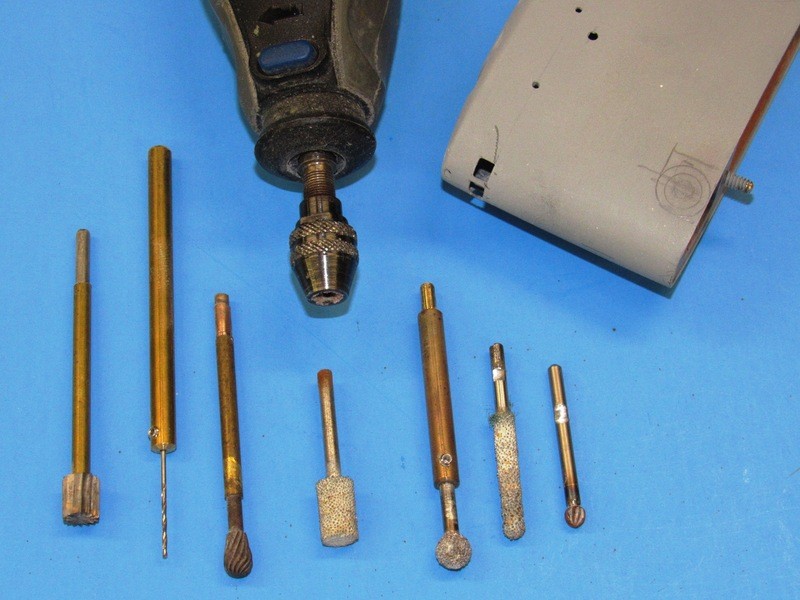
The shank-extensions are turned from 3/16� diameter machine-brass that is reduced to the 1/8� diameter at the chuck end to fit the moto-tool, and bored .128� at the tool end to accommodate the 1/8�shank of the typical Dremel rotary tool. Note that tools to be used with the shank-extension have a flat ground in, this to fit a set-screw that keeps the cutting tool from rotating in the shank-extension when serious torque is applied.
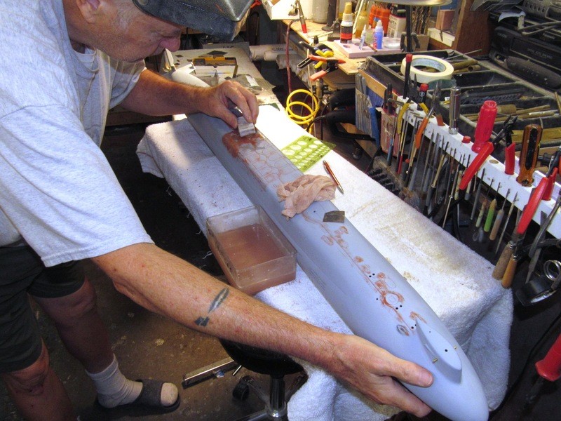
Using the shank-extension to get the rotary burr up and behind the deadlight openings, thinning the frames to a more scale like thickness.
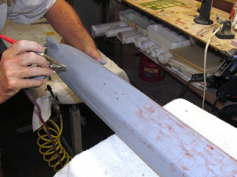
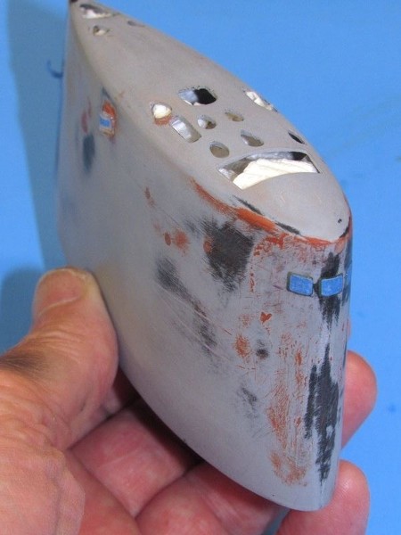
Those holes in the sides of the sail will soon go away. They are for alignment and temporary fixture of the internal mast foundation piece � made removable to facilitate establishment of the registration between top-of-sail mast openings, and the openings in the mast foundation. That work done I�ll glue the foundation within the sail permanently, fill the holes, and proceed with another coat of primer to the sail, but only after I�ve masked off the deadlights, emergency stern light lens, and two running light lenses with little strips of masking tape.
The door outline on the port side of the sail denotes where we got access to the control room and bridge from topside. A RenShape hemispherical �bulge� would be added to the port base of the sail and around it the outline of the door fairing would be scribed in.
You can just make out the WEBSTER�s unique bow planes in the background of this shot. As the guys in this picture are in dungarees I assume this shot was taken as these guys were either underway on a pre-patrol shake-down or swapping piers at Apra Harbor.
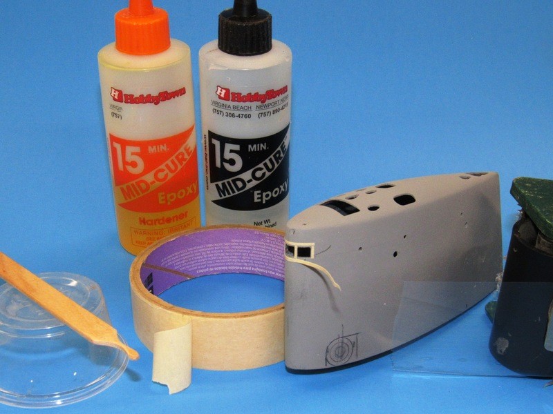
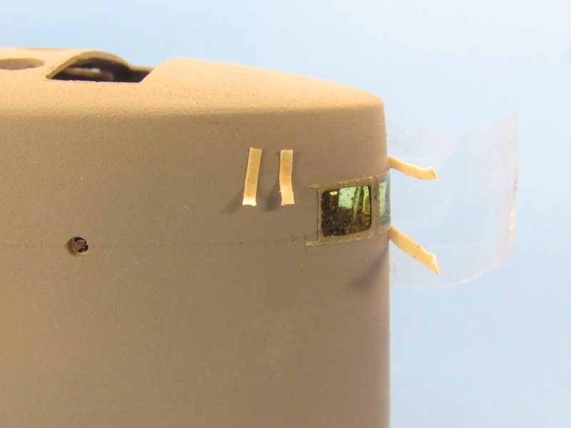
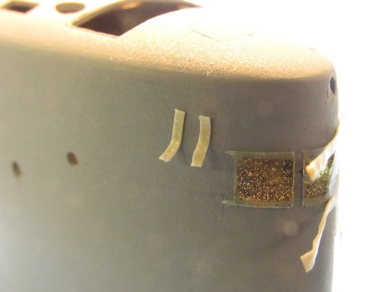
The David Manley method of representing practical clear deadlights is to open up the frames, back the front end of the sail with tape (the clear packing tape you see to the extreme right of the shot), and from the inside of the sail apply some catalyzed clear epoxy, laid on as two or three coats, permitting each to cure hard before laying down the next. You leave it to capillary action to draw the glue into the edges of the frames and over the backing tape.
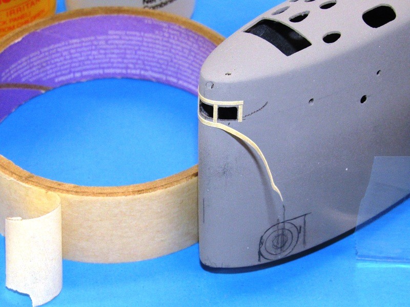
The tan masking tape was used to make a two-layer thick strip of tape, pieces cut and used to build up a raised edge around the deadlight openings � this producing a void above the surface of the sails leading edge that would accommodate the epoxy, insuring that there will be epoxy to shave away, not add, when it came time to abrade the clear epoxy deadlights into conformity to the surface of the sails leading edge. Well � that was the plan, anyway!
Over the stand-off masking tape strips and leading edge of the sail was placed a piece of clear packing tape � this being the means of giving rough form to the outside surfaces of the eventual epoxy resin deadlight lenses.
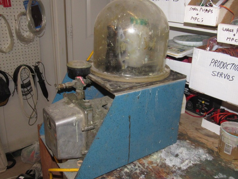
15-minute epoxy glue was mixed up, applied within the sail and shoved around with a little stick to get it to fill all the deadlight openings. The sail was then set atop my vacuum table, leading edge down, and subjected to a hard vacuum for ten-minutes. The hope was that the expanded entrapped bubbles within the glue (a consequence of mixing and exothermic reaction frothing) would expand, pop at the surface of the glue, and the gas evacuated. That was my hope. (The same process applied successfully all these years to resin tool making and some forms of resin casting).
The vacuum tables bell-jar removed you get a closer look at the little puddle of cured epoxy glue that gave form to the clear lenses of the three sail deadlights.
After the epoxy glue cured as hard as it was going to get I removed the big piece of clear packing tape from around the leading edge of the sail and then pulled off the masking tape strips used to put the outside face of the raw deadlight lenses a short distance off the face of the sails leading edge. And this is what I got.
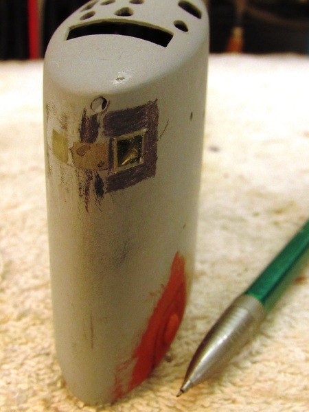
And now � let�s back light this thing: WHAT A MISERABLE JOB!!!! Just look at all the little bubbles captured in the epoxy glue deadlight lenses. God Damit!
Clearly, pulling a vacuum on the glue before it changed state from liquid to solid did not de-air the mix any at all. It must be the thickness of the glue: even though the vacuum increased the size, and hence the buoyancy, of the entrapped gas, the viscosity of the glue overcame the buoyant force of the enlarged bubbles that would have pushed them upward to the surface, breaking, and giving up the entrapped gas to the vacuum.
Here�s what I think happened: As I only had ten-minutes to hold vacuum it clearly was not long enough to get those bubbles to migrate from mix to surface. The obvious fix is to use a thinner formula adhesive � one where the bubbles can travel the required distance in the given time. And/or use an epoxy of much longer pot-life. I�ll kick this thing. Maybe the next project will benefit from these findings?
I�m going with this as is, tiny bubbles and all. One must, from time to time, be pragmatic and accept things as they are and move on. Otherwise projects never get completed. You rivet-counters, procrastinators, and project quitters know exactly what I�m talk�n bout!
Even though I took the precautionary measure of building up the epoxy deadlight lenses a bit proud of the sails leading edge surface I still failed to completely build a height of epoxy tall enough to avoid a few divots, like those you see in the center deadlight lens. This was fixed by a few drops of epoxy glue applied to each divot and, once that had cured hard, filing the repaired areas flush.
To guide me � keeping the file from digging into adjacent work as I took the lenses down to conform to the sails leading edge � I marked around the epoxy areas with a pencil. When the file got the lens almost even with the surrounding sail structure I would observe the start of file-marks on the penciled areas, telling me to stop with the filing and continue the work carefully with descending cuts of sandpaper backed up with a sanding block.
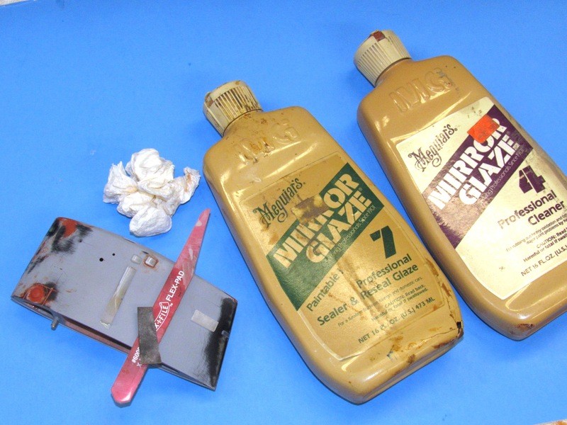
The three deadlights were sanded with descending grades of sandpaper and sanding sticks till I got to 2000 grit. I then switched to paste type fine abrasives. My favorites are #4 and #7 Mirror Glaze water-based polishing compounds. By time I had finished rubbing down the clear parts with the #7 they had assumed an acceptable level of opacity � little bubbles and all!
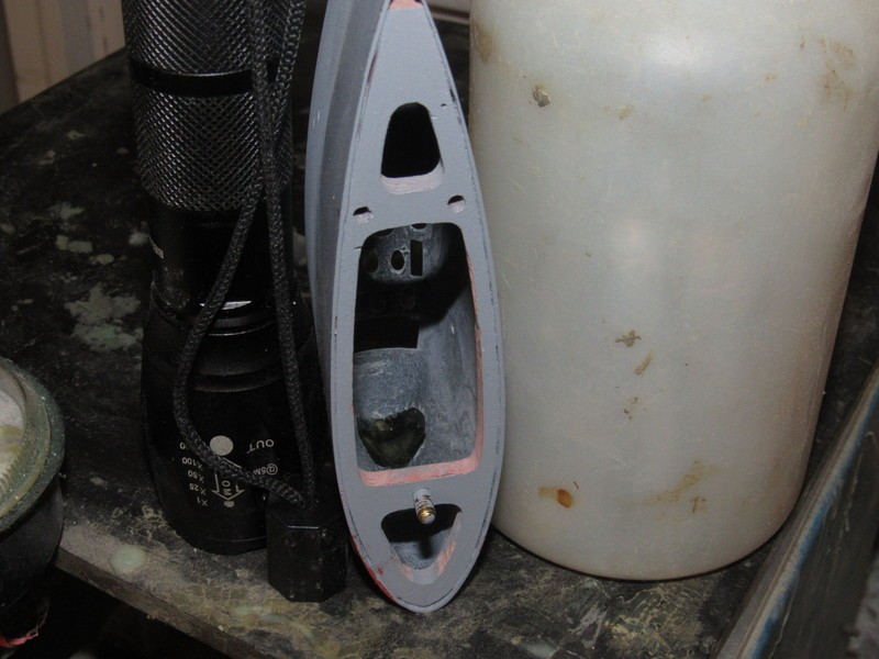
The two streamline-shaped port and starboard running light fairings were cut from a piece of clear acrylic, which you see sitting on the sail in this shot. These items also received the sanding-polishing treatment till they were optically clear. Note that sitting near the trailing edge of the sail is another piece of acrylic that will be narrowed and inserted into a slit. That item becoming the lens of the emergency stern light.
For small polishing jobs like this I simply remove the caps from the containers of the two grades of polish and take what I need from within those -- the very gritty #4 to the left, next to it the fine #7. I had to re-polish the installed running light fairings after fairing them to the sail with small amounts of putty � sanding back the dried putty scared them a bit.
A trick I learned from the model aircraft guys: Precision application and rubbing in of the polish over clear parts is best done with the end of a modified popsicle stick. The wet polish causes the wood fibers to separate into a sort of stiff-brush at the tip, soft enough to evenly rub the polish over the work, yet hard enough to permit exacting control over the areas that need the elbow-grease.
Before I could address the alignment and screw holes marring the sides of the sail I first had to permanently mount the internal mast foundation piece by CA�ing it in place; removing the temporary alignment pins and securing fasteners; filling the holes with CA and baking soda; grinding that down; applying putty and sanding that down; and then FINALLY! moving on to priming the entire sail structure.
Note that I first painted the mast foundation piece black before installation as once it�s in place it would be hard to paint.
Ready for primer. I�ve applied masking tape over where I want to preserve the clear deadlights, running light lenses, and emergency stern light lens. Note some of the photos I used to fine-tune the placement of detail items on the sail.
Primary documentation that supported this project included my personal copy of the training aid booklet (TAB), issued to each crewmember as part of his qualification/re-qualification package when reporting aboard (my copy issued me nearly half a century ago). I also made use of released �booklet of general plans�, and dry-docking plans specific to the LAFFAYETE (SSBN 616) class -- documents de-classified and available to the general public for several decades now.
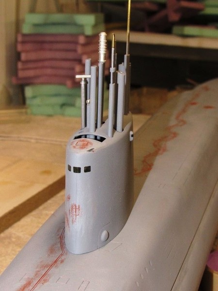
To prevent overspray of primer and paint from getting onto the internal mast foundation and inside surfaces of the deadlights I stuffed the upper portion of the sail with paper towel shreds.
Note how I made the actual clear parts of the deadlights a bit larger than they had to be � this insures no structure can be observed through the deadlight framing of the painted model � the masked portions of the deadlights cover exclusively clear lenses.
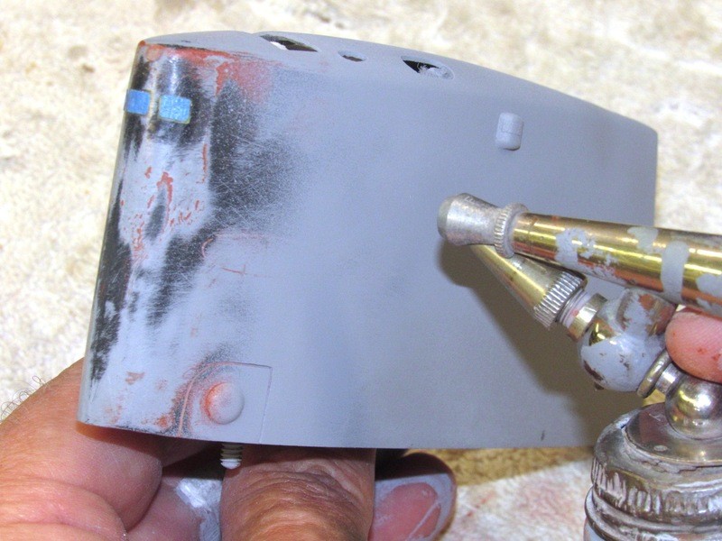
Primer gray: the great EQUALIZER!
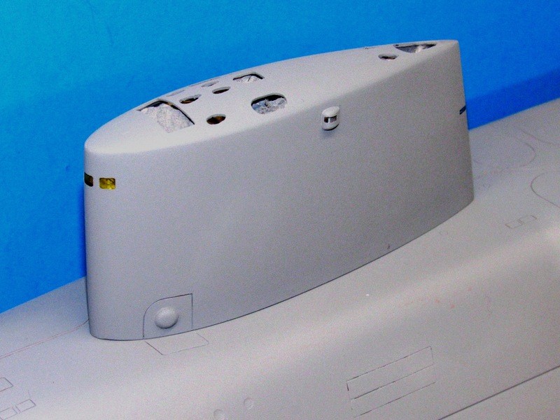
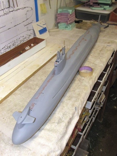
Primer down and the masking removed (which will be re-applied when it comes time for painting, weathering and clear coats). Sitting atop the hull, things are starting to shape up!
Still some scribing to do on the top and sides of the sail, but most of the work on this structure is done � if you discount all the fiddly stuff remaining on the fairings, periscopes, and antennas. Groan!
Nothing to do with scale, but I still have to fit a practical float activated snorkel within the sail. An element of the SemiASperated (SAS) ballast sub-system I employ on almost all my r/c submarine models. More on that later.
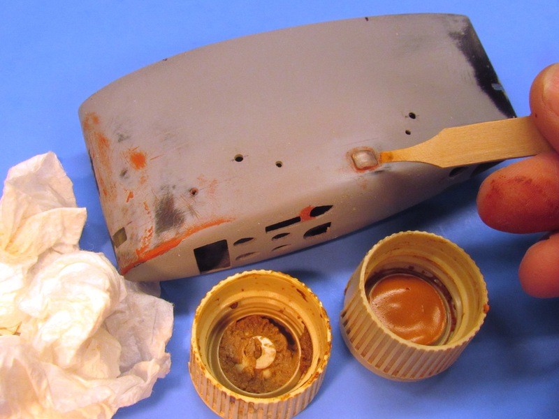
Top notch, David. Speaking from experience, the "screw on" attachment method for the sail allows for easy access to the float valve / painting & finishing / repair work on the sail / etc.
Well, even the greats -- like me -- make mistakes.
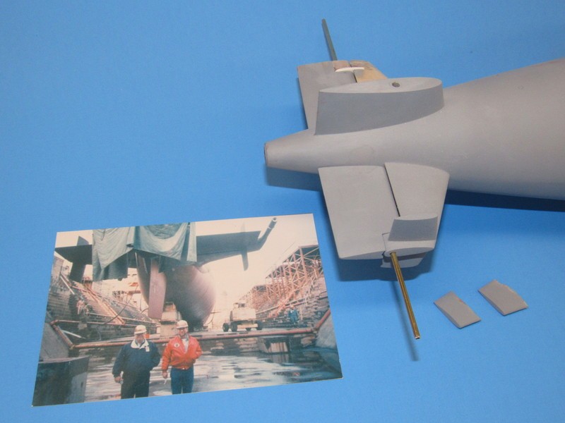
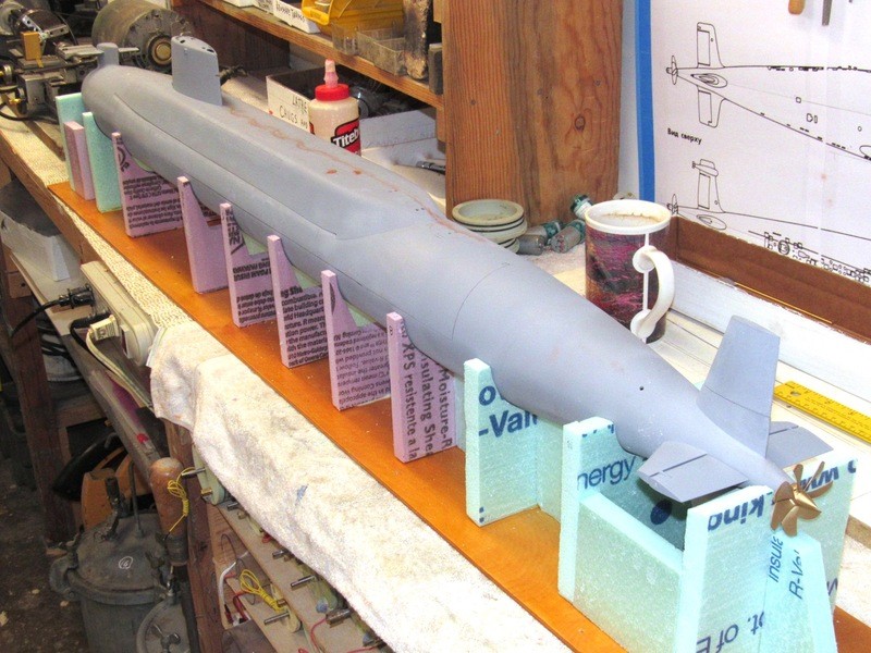
Such is the case with the stern vertical stabilizers I, as it turned out, erroneously mounted at the tips of the horizontal stabilizers on my 1/96 scale model of the DANIEL WEBSTER, a unit of the LAFAYETTE class of SSBN�s produced in the early 60�s.
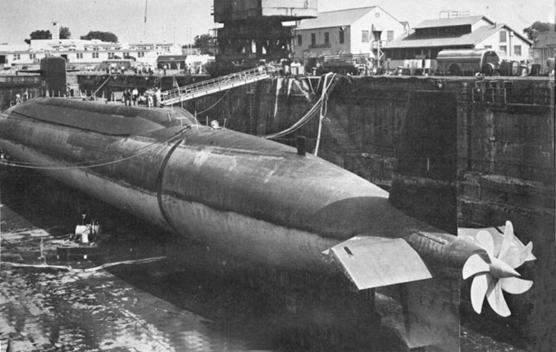
Below is a dry-dock photo of a LAFAYETTE class SSBN, clearly showing the absence of vertical stabilizers and the distinctive split upper rudder, classifying features of the class.
Note that the outboard stern plane operating shaft bearing is near the outboard tip of the planes. As the stern planes on most modern American submarines are of the �balanced� type � a significant fraction of the plane surface is in front of the center-of-rotation � the inboard and outboard operating shaft bearings are situated well aft of the control surfaces leading edge. To achieve that, some boats, the LAFAYETT�s specifically, employ an outboard bearing support arm, or post, fixed to the horizontal stabilizer, that extends aft into the stern plane and engages its operating shaft. That arrangement well illustrated here.
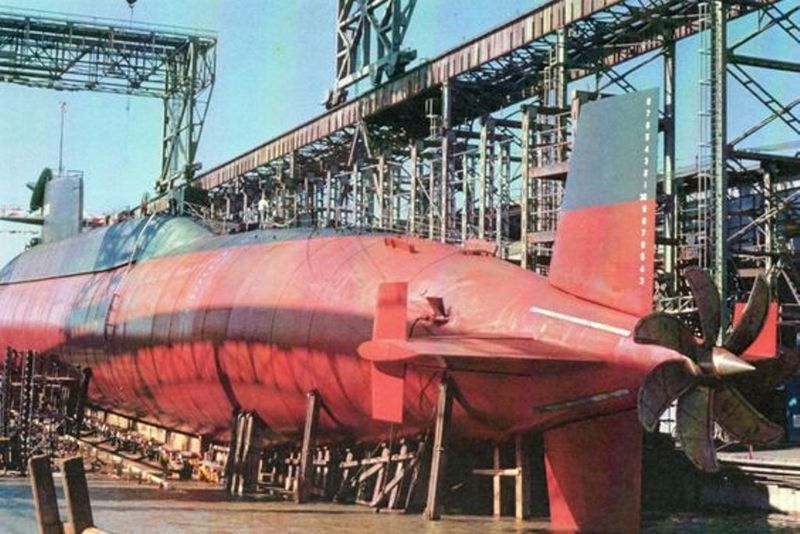
The location of the stern plane outboard operating shaft bearing is the big difference between the LAFAYETTE and BENJAMIN FRANKLIN class boats � the much wider, tip located operating shaft bearing structure on the BENJAMIN FRANKLIN class boats providing the foundation upon which the vertical stabilizers are affixed. I�m not sure if the vertical surfaces were employed as housing for sonar elements (early PUFFS?) or not, but they did greatly improve the dynamic stability of the submarine about the yaw axis � meaning less work for the helmsman!
The Scale Shipyard 1/96 kit I�ve had all these decades therefore represents the BENJAMIN FRANKLIN, not the LAFAYETTE class SSBN, as I had mistakenly assumed. The three major physical differences between the two classes is the location of the planes on the sail (a moot point on my DANIEL WEBSTER model, as it had those planes mounted over the bow); the use of a fixed vertical stabilizer under the upper rudder, and the absence of vertical stabilizers on the LAFAYETTE class boats.
It was all there in my documentation: my qualification notes, dry-dock planes, booklet of general planes, and several photos of the DANIEL WEBSTER and other LAFAYETTE class SSBN�s in dry dock. If I only paid attention to that I would not have found myself chasing my tail as I fell down the rabbit-hole of, �gee! � looks neat, let�s stick those on the ass-end of my toy submarine!�
As a closer look at my documentation revealed, those vertical surfaces were a feature of the later BENJERMAN FRANKLIN class of SSBN, not the LAFAYETTE class of which my DANIEL WEBSTER was a member.
I erroneously assumed (NEVER assume!) that some boats, including my boat, got these as a yard-period retrofit. I have found nothing to substantiate this assumption. So, the damned things I worked so hard to install had to come off!
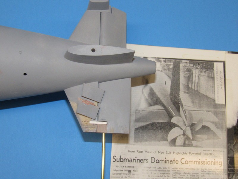
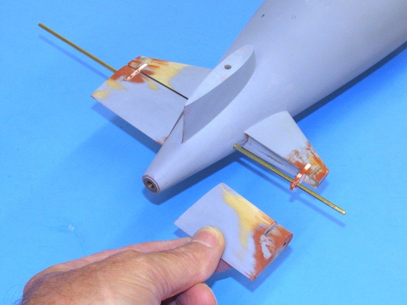
So -- to better illustrate the difference in how the outboard stern plane operating shaft bearings were situated between the two nearly identical classes of SSBN�s -- I halted the work after most of the change was done on the port side, but not yet done to the starboard. This illustrates the difference between the two configurations.
Note the two snipped off vertical stabilizers in foreground (sob, sob � sniff, sniff).
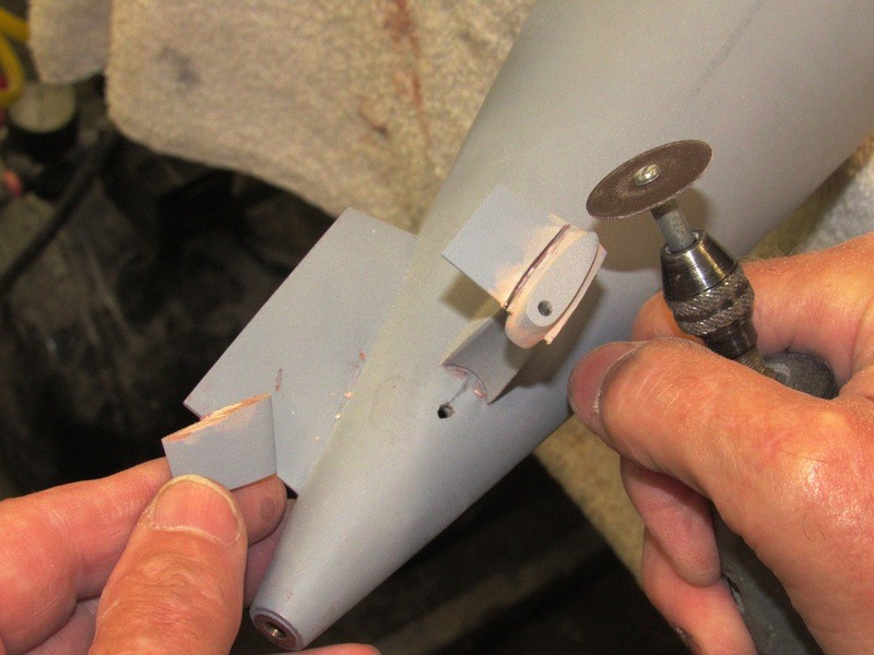
As the vertical stabilizers featured a G-10 fiberglass core that ran through the bearing foundation I found the best tool for removing them was a thin-blade, un-reinforced carbide cut-off wheel. The rough work done, the roots of the vertical stabilizers were ground down with carbide burr, flat files and a sanding block.
It�s so much easier to destroy than to create.
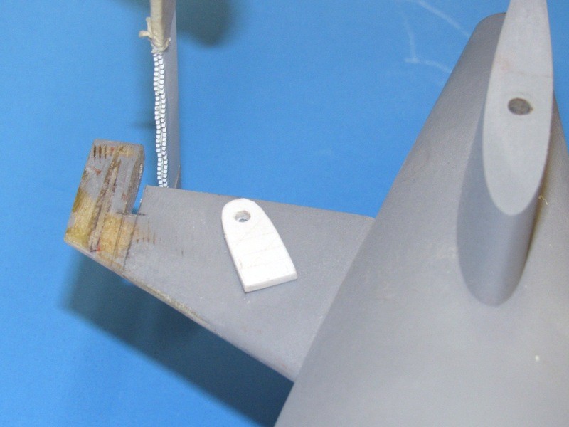
When kerf is our friend: The width of the stern plane operating shaft outboard bearing posts at this scale came in at a bit over 3/32�. To achieve these slots in the horizontal stabilizer and stern plane I found that taping two hacksaw blades together and using this tool to saw the slits was the best solution to the problem. The bearing post itself is a piece of Sintra plastic sheet cut to shape and drilled at its end to pass the stern plane operating shaft.
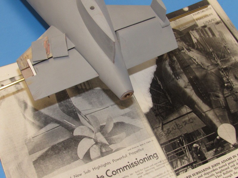
The vertical stabilizer foundation was cut back to the trailing edge of the horizontal stabilizer and the concave trough that nested the leading edge of the stern planes was roughed out with round files. The void at the tip of the stern plane was built up from RenShape and worked to shape.
The gross filling and contouring was done with Bondo, followed by air-dry touch-up putty, and lots of sanding. Only then did the fist coat of gray primer go down to check the work. You see how the stern plane operating shaft slips through the two bearing points � one bearing point at the hull, the other at the outboard bearing support arm. A set-screw in the stern plane makes it fast to its operating shaft, the torsion force to move the stern plane is through an internal yoke that makes up to both operating shafts and affords clearance of the centrally running propeller drive shaft.
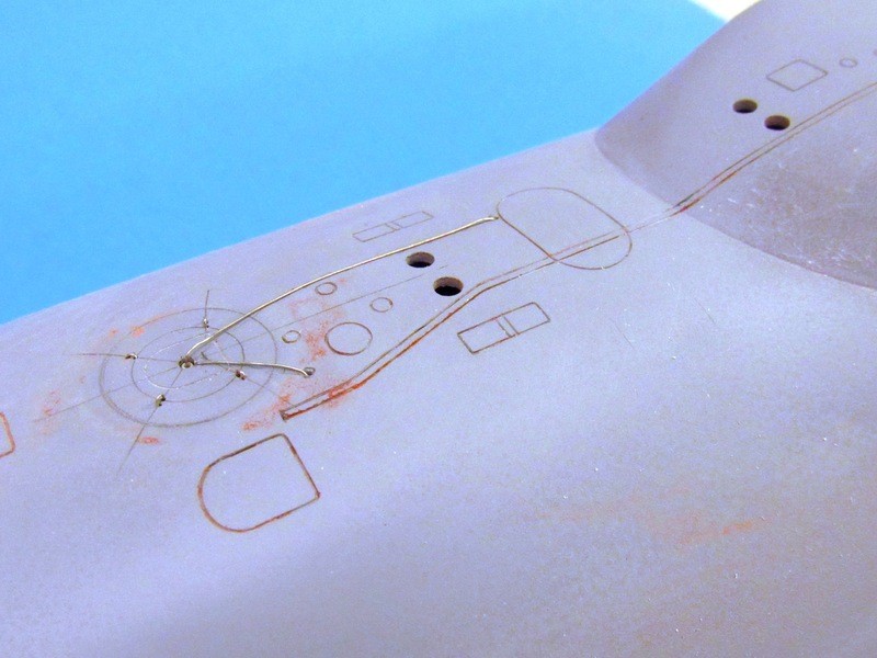
All modern American combat submarines up to the LOS ANGELES class featured one or more escape marker-buoy systems. In the event the submarine is grounded at a survivable depth (in reality that means pier side, or just well within the continental shelf) the marker buoy is released and rises to the surface, as it does so an attached �down-haul� cable is paid out, the cable running through a �bail� or fairlead situated over the escape trunk hatch, dead center of the surrounding seating ring that would be used to make the water tight seal between McCain rescue bell or DSRV skirt and the stricken submarines escape trunk.
The down-haul cable is wound on a drum set in the superstructure near the escape trunk upper hatch. On the model I represent the short length of down-haul cable running from the drum, up through a fairlead hole in the deck, straight to the escape hatch down-haul cable bail. Another wire, coming out the top of the bail runs to the escape buoy marker.
While I was at it I inserted the four hold-down padeyes that circled the escape hatch and sat within the seating circle � these artifacts from the old McCain rescue chamber system. All the required holes drilled, wire fitted and checked, it was all taken apart and set aside until all painting and weathering had been completed on the model.
If you�ll indulge me, here�s a brief departure from this WIP discussion of the nuts and bolts of assembling the Scale Shipyard 1/96 DANIEL WEBSTER kit. A look at the means I employ to protect my submarine models between shop and lake.
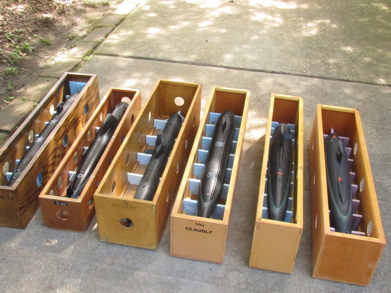
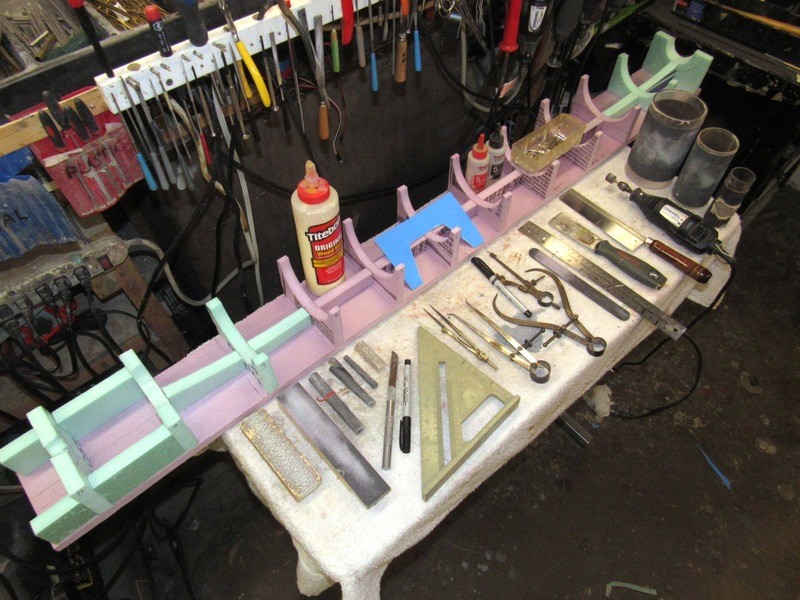
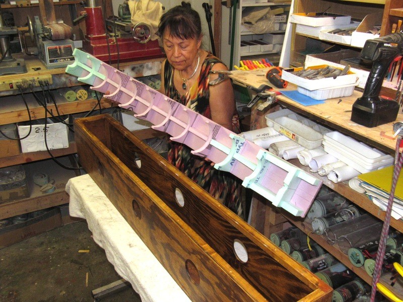
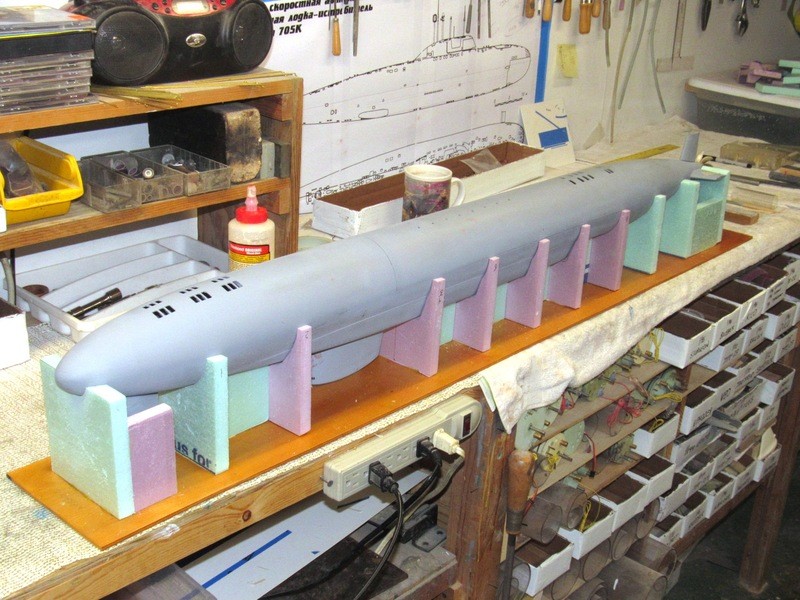
Below are just some of my ready-to-run r/c submarines in their protective boxes � the lids removed to present how foam sheet is used to center and cradle the model within its box, protecting it from banging around inside regardless of accident or rough handling.
First step is to make a wooden box � if you can�t figure how to make a wood box you are in the wrong game! Note the holes in the sides of the boxes to insure quick drying of the wet model hull within after a day�s play. The removable lid is secured with deck-screws.
I�ve found that �� thick exterior-grade plywood is fine for the sides, top, bottom, and ends. The corners are internally reinforced with 1� square molding. The pieces are secured with finishing nails and wood-glue. The surfaces, inside and out, are sanded, stained and receive many coats of polyurethane varnish to make the wooden structures water-proof.
Presented in this installment is a vital peripheral aspect of what it takes to store, protect, and transport a delicate display model once the hard, exacting work is completed. A bit more work, but an effort that will insure an undamaged model be it in storage at home, on the road to a boating event, or carried between van and waterside display-work table.
It�s not enough to leave the model in a box to rattle around. No. A padding of sorts; something to suspend the model within the box � rigid enough to hold the model, but soft enough not to abrade against the model, damaging its parts or finish � is required. I found that foam insulation board, available at just about any big-box home-improvement store, is the ideal material for the suspension of the model within the box. This expanded foam sheeting is easy to cut, is reasonably rigid, takes to epoxy and water-soluble glue well, and can be mocked up with pins to validate fit before bonding with glue.
The internal padding takes the form of an upper and lower piece that sandwich the model between them. The lower padding piece sits on the bottom of the box, and the upper padding piece is glued to the inside of the box lid.
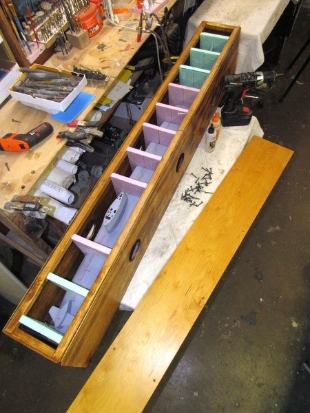
Each piece is composed of frames and keel pieces. Each frame cut to the correct form to closely girdle the model at that station. The foam padding elements are either cut to shape on the band saw or sharp knife, with fine-tuning of shape with sanding tools.
The internal padding is divided into two pieces: one-half that sits within the box, and one-half that is glued to the bottom of the removable lid. The model sandwiched between the two halves of the padding when the lid is screwed down in place.
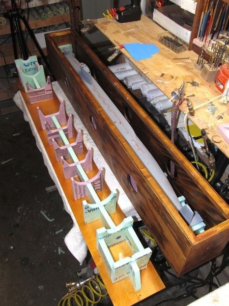
In the case of the lower padding piece, its frames are glued to a foam base that is sized to fit the bottom of the box. All work is done off-box, giving me unobstructed access as I insured proper fit of each foam frame to the model. Initially I pinned the frames to the foam base to mock things up as I check for fit. Once happy, the frames were glued to the base with 5-minute epoxy adhesive. Further strengthening the lower padding, pieces of foam sheet were glued between frames to form a �keel� to increase the foot-print between padding and model.
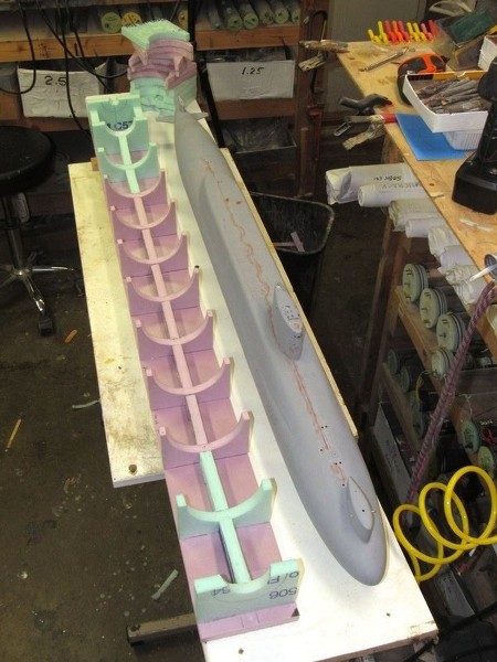
Most modern submarine hulls are simple body-of-revolution in form. So, most of the framing for the lower padding piece comprises frames with semi-circles cut out of their centers. You can make out those frames in the background. The frames for the upper half of the padding is of slightly more complex shape, that conforms to the missile-deck geometry � each one of those frames cut with the aid of a paper template whose shape was unique for its particular station along the length of the models upper hull.
One reason I make the masts of a model submarines sail removable is to keep the height of its storage-transportation box as short as possible. When in the box the masts are stowed in a plastic bag, that bag tucked into a cubby-hole somewhere out of the way within the box.
Ellie�s placing the lower padding piece into the bottom of the box, an easy operation. This half of the padding is wild � no glue is used to hold it in place. If any repair or modification to the lower padding piece is required it can be easily accessed. However, the lower padding piece stays in the box unless the need arises.
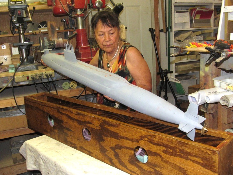
A test fitting (one of many): the model being placed into its storage-transportation box. You can just make out elements of the lower padding piece through the big ventilation holes set into the sides of the box. After the lid is screwed down on top of the box, the model is sandwiched between upper and lower padding pieces, securely and safely suspended within its box.
(Ellie and I were dating a few months before I transferred off the DANIEL WEBSTER and actively joined the diving community. So, that boat is an important touch-stone to the both of us. I fondly remember sharing with Ellie a few evening meals aboard while the boat awaited her trip up-river to Electric Boat for conversion to the Poseidon missile system).
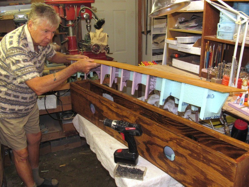
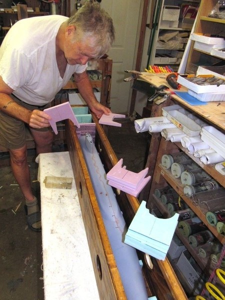
Assembly methodology for the upper padding piece is a bit different: Each frame is cut out and placed into the box that has already been outfitted with the lower padding piece and model. Knife and sanding block used to shave the top edge of each frame even with the plane of the box flange.
To hold each upper padding piece frame temporarily in place within the box T-pins affixed an upper frame to its counter-part of the lower padding piece. Later, after the upper padding frames (glued to the inside face of the box lid) are pulled away from the box, the pins slip away and are removed.
With all the upper padding frames in place it was a simple matter of mixing up some epoxy glue, smearing it over the top edges of each frame, then screwing the lid down tight and waiting for the glue to harden, bonding each frame to the inside face of the lid.
Removing the lid I inverted it and placed the model in it to check for fit. I then glued keel pieces between the frames to further strengthen the structure and provide more bearing surface to better suspend the model within the confines of the box.
Note the absence of frame and keel-piece where the bow plane structure and sail fit. Same design care was taken at the stern to provide clearance for the rudder and propeller.
As you can see, the upper padding structure -- when inverted and set on a table -- makes a useful model cradle.
Enough of the ooh's and aww's and the self righteous I am the master stuff, get back to building!
(Just trying out some new approaches here - not sure it fits me LOL)
If you can cut, drill, saw, hit things and swear a lot, you're well on the way to building a working model sub.
Enough of the ooh's and aww's and the self righteous I am the master stuff, get back to building!
(Just trying out some new approaches here - not sure it fits me LOL)
Though the GRP hull of this kit was found to be a very accurate representation of the 616/640 class, it does suffer in form, to a small degree, due to the method of fabrication. Obviously the fiberglass hull halves were given form in hard-shell type tools (molds) as there are the usual artifacts presented indicative of that process: The depth and fidelity of the engraved lines (that denote missile hatches, line-locker hatches, retractable cleats, escape marker buoys, etc.) are weak; and those engraved lines closer to the edge of the hull half get ever shallower and less distinct of form. And � becoming the subject of this WIP installment � the deeply indented longitudinal undercuts that denote the break between the upper hull and missile deck (superstructure) is way too shallow and the terminus and fairing at each end did not poses the clear definition seen in pictures of the real boats.
Below illustrates the materials and techniques employed to build up the stern and bow transitions between hull proper and missile deck -- a deliberate re-contouring of the GRP hull to overcome the short-comings of hard-shell tool use -- in order to achieve a more scale-like look to the display.
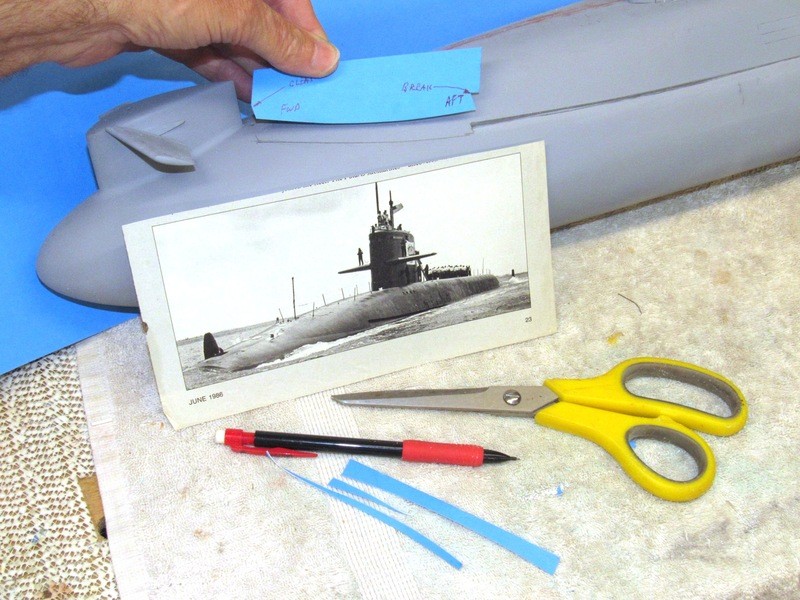
The photo of an SSBN underway clearly shows the fairing plate that transitions the forward portion of missile deck into the bow � the lower edge of that plate evidenced as a line curving upward from the missile break up to the forward set of cleats.
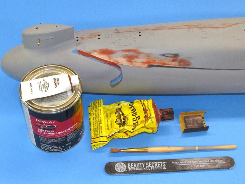
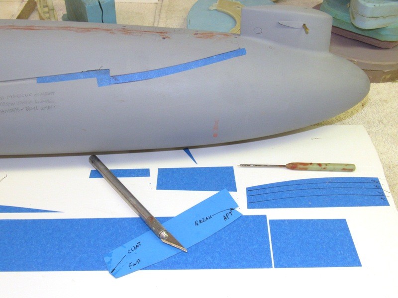
To be fair, the raw GRP hull kit did indeed represent this transition line, but it was of little prominence and most of it lost during sanding and priming in preparation of painting. So, I began the process of building up the seam between forward and after hull and the transition fairing plates. First thing was to identify the forward and after transition plate lower edge angle and make paper templates. Using the templates I laid down pencil lines that would be followed as I applied masking tape to define the slightly raised edges between fairing plate and hull.
From the templates I cut curved strips of masking tape used to keep the filler/putty off the areas of the hull I don�t want it. It�s the edge of this tape that produces the sharp, well defined edge representing where the fairing plate starts and the hull ends. The scribe is used to push back filler/putty from the upper edge of the longitudinally running missile break and its tight radius transition to the vertical where hull and fairing plate meet.
The height of the plating is driven by how many layers of masking tape are used. Initially, as there was a significant amount of under-camber to fill, I went with two layers of tape. Later, as I fined tuned the re-contoured area with air-dry putty I used a single layer of masking tape to denote the hull-plating transition line.
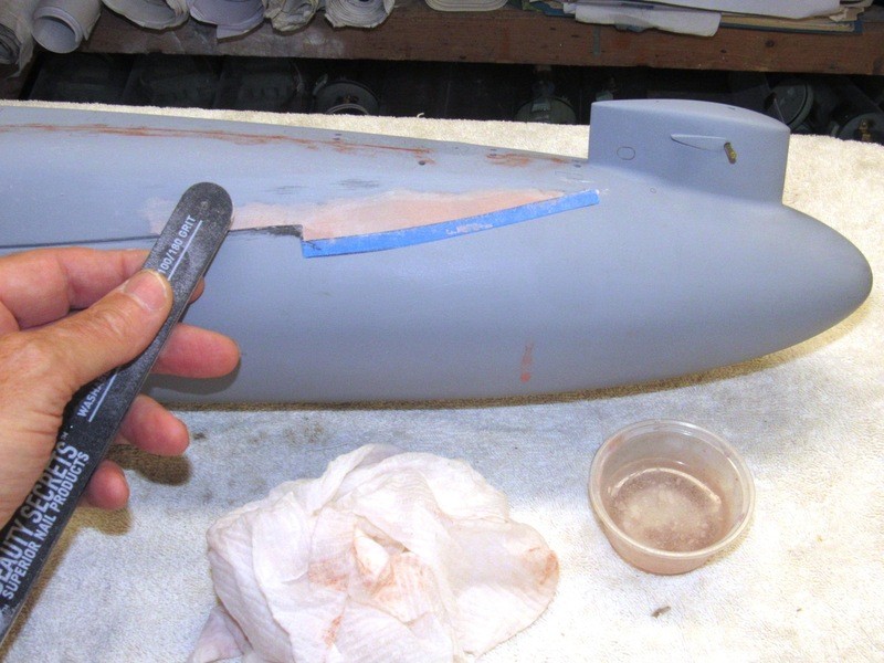
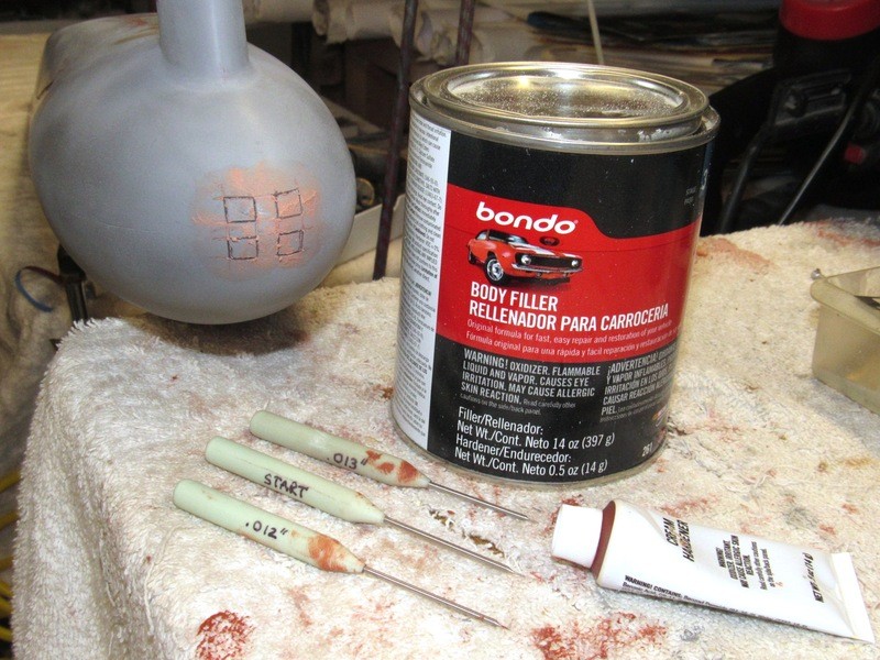
For significantly thick build-up I go with the two-part automotive filler, like Bondo. As this is a exothermic curing material � which does not rely on evaporation of a volatile solvent to change state from paste to solid -- it�s the go-to material for significant build up; such as here where I want to re-contour the forward fairing plating into the hull. After mixing, the filler is laid on with a putty knife and once it�s hardened significantly it�s wet-sanded down to the height of the masking tape and a feather-edge to the hull with a #200-grit sanding stick (available from beauty supply houses). A damp cloth removes sanding grit as I work.
After sanding and thoroughly drying the work, it�s important to over coat the porous two-part auto filler with a skin of CA adhesive � the CA wicks into the filler increasing the bond between it and the substrate and also serves as a reasonably effective water barrier � this is, after all an r/c submarine that will be getting its fair share of water time at the lake.
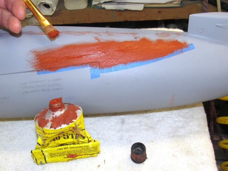
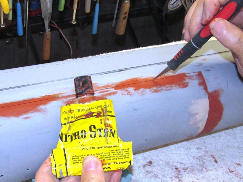
Once the CA skin is lightly sanded, fresh pieces of masking tape are applied and the work over coated with an air-dry touch-up putty � the Nitro-Stan 2001, red being my favorite. Care is taken to remove the masking before the putty comes anywhere close to drying.
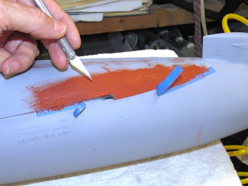
Note that application is with a brush, straight out of the tube. While still wet the scribe is used to push putty back from the missile break lines, and the masking removed.
The putty went down in a well stroked manner so as to keep its thickness down. The thicker you apply air-dry putty, the longer it takes for the solvents to leach out of the goo; the longer it takes for the stuff to harden. Once hard the work was initially wet-sanded with #240-grit, followed by finishing strokes with #400-grit. At this point, the work was ready for a check-coat of primer gray. Problem spots were addressed with more putty-sanding-priming.
The seemingly never ending job of identifying scratch, marks, bumps, and voids and addressing them with putty and sanding tools continues until gray primer reveals no imperfections. For those spots that receive filler or putty that bridge gaps between the two hull halves I took care to slightly drag the knife point of a #11 X-Acto blade into the seam to insure I didn�t inadvertently bond the two halves together. This done, of course, before the filler or putty sets hard.
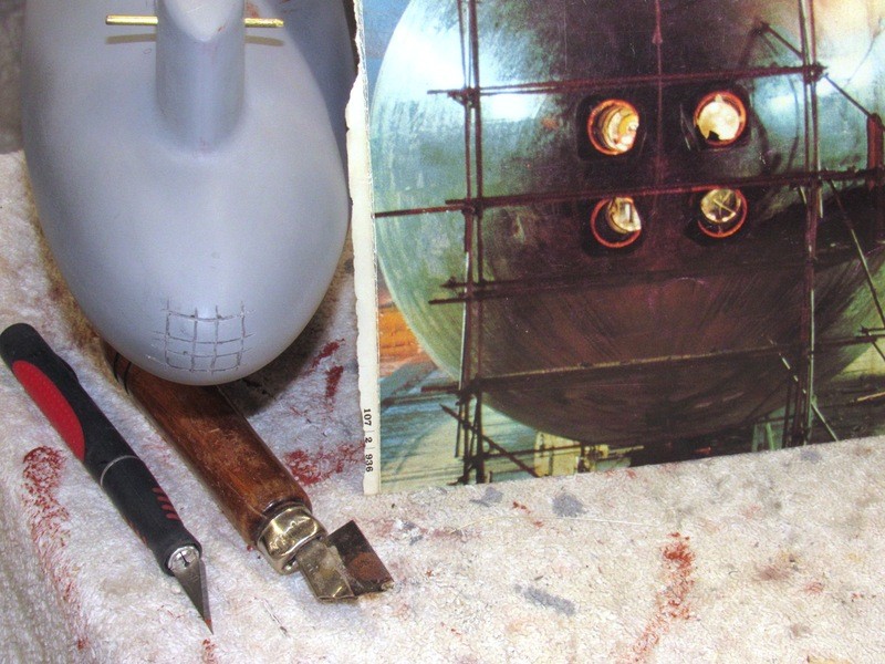
An artifact of GRP parts produced in hard-shell tooling is that the depth and width of the engraved items diminishes the farther they are from the top of the upper hull, or bottom of the lower hull. Such was the case with the barely visible engravings representing the four torpedo tube shutter-doors at the bow of the model. To insure that the horizontal and vertical lines that defined the door shared the same plane as its adjoining mate I simply razor sawed four vertical slits and four horizontal slits, all slits long enough to cover a set of shutter-doors.
Tic-tac-toe � I win!
Guiding me as was this excellent picture. A view, in dry-dock, of a 640-616 class boat -- tube breech and muzzle door interlocks broken -- with torpedo room lights shining through. A beautiful picture that is guaranteed to give all submarine qualified Torpedoman the jitters!
The gross cross-cuts and desired scribing were both filled with catalyzed Bondo, rubbing the goo into the deep groves with thumb and fore-finger. Before the filler could set I scribed out the torpedo tube shutter-door engravings. Later, after the filler had hardened, I filed and sanded the Bondo even with the contour of the bow. I then laid down some air-dry touch-up putty, chased that out of the shutter-door engravings and later sanded that work down smooth.
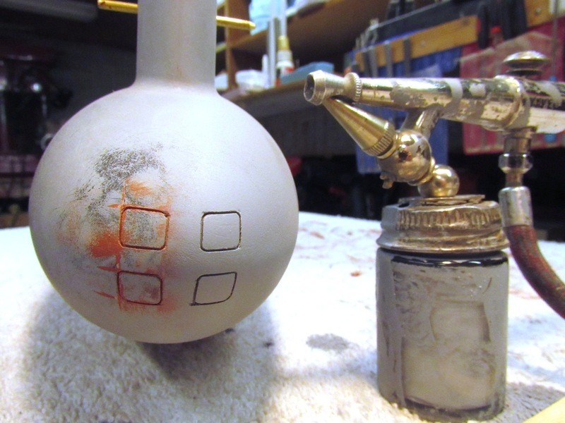
The shutter door engraved lines are still pretty ragged, as this first shot of primer gray reveals. A bit more filler, careful work with knife and scribes, and I�ll have these engravings looking good.


Comment