
As I stated I have finally started my Pt-109 conversion to rc. Is this a clever move? Well time and tide will tell.
So after gathering some background research came the gathering of parts needed for my first go at a solo conversion, i.e no pre-established fittings kits or internals. However I am sure that you blokes will guide. nudge, push and tell me if I have gone astray. Although looking at how far I am into the build that might be a mute point... As far as assembling a model goes I reckon I have got that down pat. I mean how hard can putting this boat together be...? Anyway from the outset I had decided to run it with three props n motors much as the full scale. This is what I went with, 3 x JR 400 series suppressed motors these I would then attach directly to the prop shafts via some flexible tubing. The props and shafts are from Raboesch. I am using the water proof ones with a bushed strut and 2mm shaft and 20mm type D No 152 brass props. Behind these will be the rudders, which even though they are the minis the look a little big on the kit. I am powering the motors off a 7.2 4600mha Ni-MH pack through a Mtronicks 30 amp speed controller. If my maths is correct the motors combined shouldn't pull more amps than that so I reckon I be good with that. The receiver is a corona 6 channel I had in stock and a standard ball bearing servo to run the rudders....
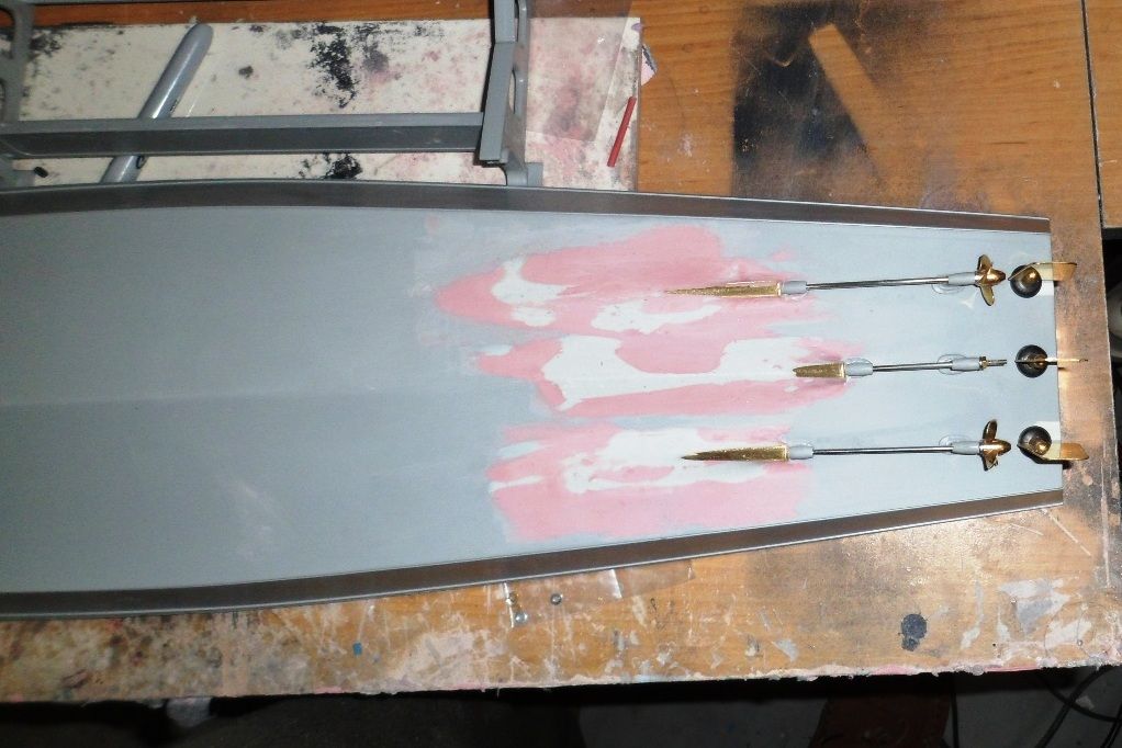
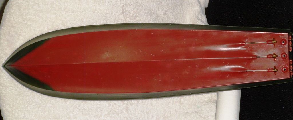
It kind of made sense that the first step would be installing the prop shafts, rudders and electronics. My inexperience in this area was certainly a telling mark as I didn't realize how much of the keel I needed to remove in order to get the shafts and housings I had bought to sit at the correct angle. Which I gauged by using the kit prop struts as my guides. What I then did was use a two part putty pressed in and around each shaft housing. which I then shaped sanded followed by some blade putty to get the final contours and low spots sorted.
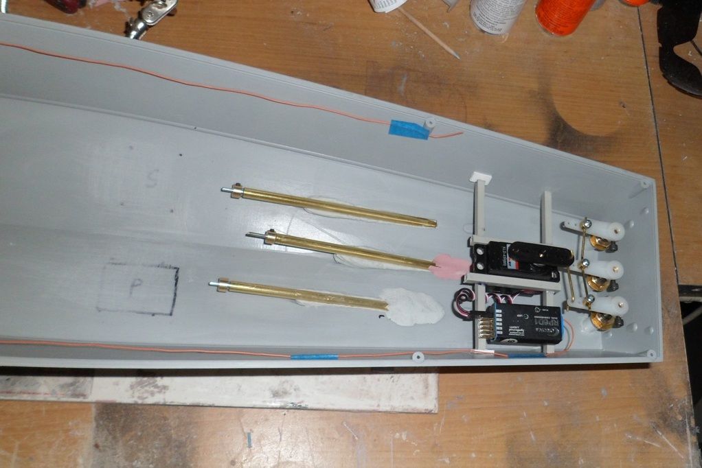
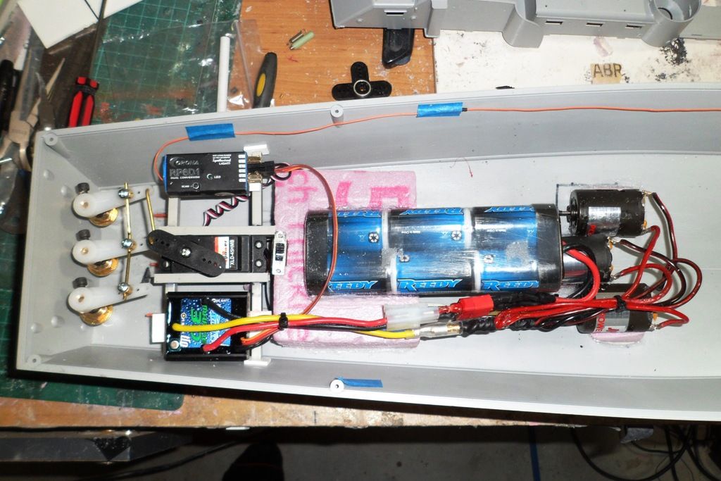
That took just over a week to do. Next on the do do list was mounting the servo, speed control and receiver supports. I decided to go with hollow rectangular ABS bar for this so I could keep the weight down plus I know how to work this better than timber in a model build. The other thing the equipment frame will do is add some rigidity to the hull. As a static kit the hull as is more than ample but feel as an rc model a little addition bracing is needed.
As mentioned above the 'mini' rudders on this kit don't look so mini and I also needed to run them through some styrene tube acting as a long bush as the rudder shaft housing had a good 30+mm area beneath the thread to the o-ring seal and mounting base... I went through a couple of set ups for mounting the servo and rudder arms. On paper it was doing my head in and I realized I was simply over thinking it. In the end I tossed out the tiller arms that came with the rudders and picked up some control arms from my local LHS that had the ezy connects with them. So now with just one piece of 3/16th rod I was able to govern all three rudders. I then set the servo up so that a singe rod went directly down from the servo arm and through the middle tiller arm. Switched on the system then moved the stick on the tx and promptly tore the servo and bracing mounts clean off the hull!!! By then it was getting late so I spat the dummy and went to bed. Then at some ungodly hour my sub conscience through up an image of the old rack n pinion steering system in my first car and that's what I went with after rebuilding the rack/brace.
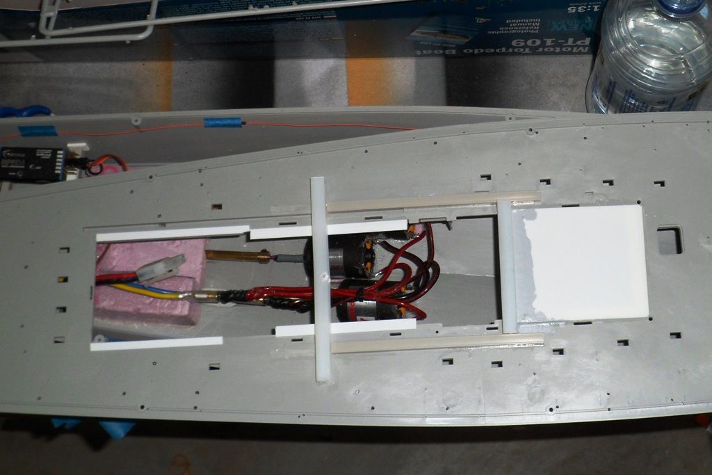
Feeling pretty pleased with myself I boldly moved on to installing the speed controller and motors. My first attempt with mounting the motors didn't go as planned. I had purchased some metal mounts for them and the plan was to fix them to the hull with countersunk bolts through the hull and the heads recessed and filled over. Firstly I didn't take into account the curvature of the keel and secondly the mounts had the motors sitting to steep for the direct drive to work effectively. After some time in trying several ways to make them work I feeling a tad over whelmed. so I downed tools and the following night did some research on the old world wide web. My final fix still seems a little odd to me but it appears to be holding with the couple of full throttle bench tests. In the end I used some dense hard foam cut down into wedges and shaped to fit both the keels conture and the shape of the motors. I then stuck each motor to the foam mount with a good dollop of silicon, tidied them up and left them to dry for a day. The next night then fixed them to the model. To make sure I got good adhesion for the silicone and mounts I used some 80 grit paper to sand the rough up the plastic as well as filing some grid lines into the foam. The next night I was thinking how clever I was to leave the main prop struts from the kit installed but the first full throttle bench test showed me the errors of my ways. The motors and mounts were rock solid but the kit struts not so. with the motors kicked in to full throttle they didn't hold up to the thrust loads so they need to be replaced. Fortunately the shaft kits came with a multipostion three armed strut bearing so all I had to do was remove two of the three supports on the bearing clean up the one broken styrene kit strut, remove the other two kit parts, then drill and file out a groove to take the new struts and bobs your uncle. With the new prop struts and bearing housing being ABS all I needed to do was use some plastic weld to glue them in and then ca and baking soda was applied on the inside of the hull to fill the gaps and provide additional support.
When that was all done I again used the foam to add a battery mount between the motors and servo. I know some body will comment about the wiring on the motors being parallel rather than series but I have had things in series fail and so take down the rest of the string due to the break in the circuit. So unless absolutely required I will always go parallel... I have still yet to put an inline fuse in the system and hard wire the deans plug to the speed controller
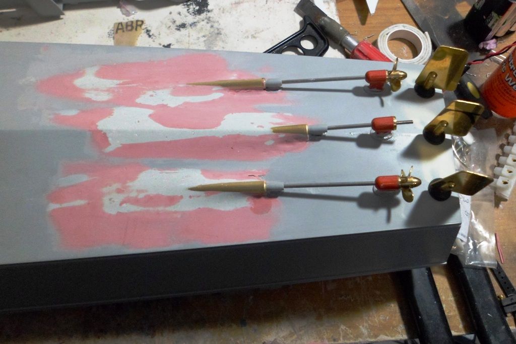
I also still have some extra filling to do around the prop shaft housings but I'll work on that after the initial primer/filler coat and I am still deciding on whether to reshape the rudders to something closer to the actual boat but as they are thin I am concerned that vibration from cutting would damage the way they are mounted to the shafts not to mention me making a botch job of it...
Feeling rather chuffed with my efforts I was quickly slapped down on how to gain internal access whilst maintaining the best water proof integrity I could. However it appears that Italeri had rc'ing this boat in mind when they designed it by having the wheel house and day cabin areas of the deck open. With that thought I assembled the main pieces of the cabins as a test to see how it would work.
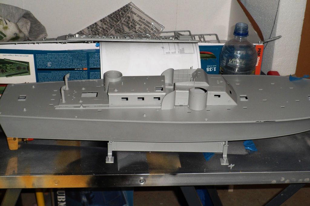
And work it just might. Firstly the deck need to be a bit more ridged so I added some rectangular I beam sections to the underside. Along with some plastruct angle as coping to help keep out any water.
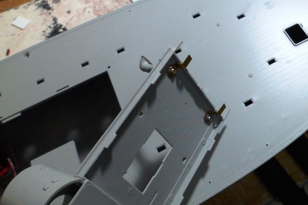
But even with the extra bracing I needed to find a way that the cabin assembly could be held to the deck and stay in place whilst the boat is under way. As it is it's not a bad fit and sits reasonably well on the deck. But that's in static mode... Being a hoarder of leftover parts, bits, fittings etc I found these two brass pieces from my robbe seawaolf sub when I converted the automatic front planes to servo controlled. A little reshaping and the screwing them in place under the two aft vent horns gives me a solid aft fixing point. I also added a klick-on in the day cabin that attaches to a small screw in the I-beam cross piece... And yes the vent is facing the wrong way they are just they were just there a test...
Here is a tops side view of the deck with the added coping to help keep out water. Eventually I will be adding styrene sheet in the gun turrets for stopping water ingress as well. Now that I have drilled out all the holes needed to add the top deck fixture and fittings in place I plan next to fix the deck in place with the screws provided and use a marine grade polyurethane sealant/adhesive as well. That way I can paint over the seal and it will add extra waterproofing too. After I add more foam to the inside as added insurance and do some tub test to check on buoyancy and how it sits.
So after gathering some background research came the gathering of parts needed for my first go at a solo conversion, i.e no pre-established fittings kits or internals. However I am sure that you blokes will guide. nudge, push and tell me if I have gone astray. Although looking at how far I am into the build that might be a mute point... As far as assembling a model goes I reckon I have got that down pat. I mean how hard can putting this boat together be...? Anyway from the outset I had decided to run it with three props n motors much as the full scale. This is what I went with, 3 x JR 400 series suppressed motors these I would then attach directly to the prop shafts via some flexible tubing. The props and shafts are from Raboesch. I am using the water proof ones with a bushed strut and 2mm shaft and 20mm type D No 152 brass props. Behind these will be the rudders, which even though they are the minis the look a little big on the kit. I am powering the motors off a 7.2 4600mha Ni-MH pack through a Mtronicks 30 amp speed controller. If my maths is correct the motors combined shouldn't pull more amps than that so I reckon I be good with that. The receiver is a corona 6 channel I had in stock and a standard ball bearing servo to run the rudders....
It kind of made sense that the first step would be installing the prop shafts, rudders and electronics. My inexperience in this area was certainly a telling mark as I didn't realize how much of the keel I needed to remove in order to get the shafts and housings I had bought to sit at the correct angle. Which I gauged by using the kit prop struts as my guides. What I then did was use a two part putty pressed in and around each shaft housing. which I then shaped sanded followed by some blade putty to get the final contours and low spots sorted.

That took just over a week to do. Next on the do do list was mounting the servo, speed control and receiver supports. I decided to go with hollow rectangular ABS bar for this so I could keep the weight down plus I know how to work this better than timber in a model build. The other thing the equipment frame will do is add some rigidity to the hull. As a static kit the hull as is more than ample but feel as an rc model a little addition bracing is needed.

As mentioned above the 'mini' rudders on this kit don't look so mini and I also needed to run them through some styrene tube acting as a long bush as the rudder shaft housing had a good 30+mm area beneath the thread to the o-ring seal and mounting base... I went through a couple of set ups for mounting the servo and rudder arms. On paper it was doing my head in and I realized I was simply over thinking it. In the end I tossed out the tiller arms that came with the rudders and picked up some control arms from my local LHS that had the ezy connects with them. So now with just one piece of 3/16th rod I was able to govern all three rudders. I then set the servo up so that a singe rod went directly down from the servo arm and through the middle tiller arm. Switched on the system then moved the stick on the tx and promptly tore the servo and bracing mounts clean off the hull!!! By then it was getting late so I spat the dummy and went to bed. Then at some ungodly hour my sub conscience through up an image of the old rack n pinion steering system in my first car and that's what I went with after rebuilding the rack/brace.
Feeling pretty pleased with myself I boldly moved on to installing the speed controller and motors. My first attempt with mounting the motors didn't go as planned. I had purchased some metal mounts for them and the plan was to fix them to the hull with countersunk bolts through the hull and the heads recessed and filled over. Firstly I didn't take into account the curvature of the keel and secondly the mounts had the motors sitting to steep for the direct drive to work effectively. After some time in trying several ways to make them work I feeling a tad over whelmed. so I downed tools and the following night did some research on the old world wide web. My final fix still seems a little odd to me but it appears to be holding with the couple of full throttle bench tests. In the end I used some dense hard foam cut down into wedges and shaped to fit both the keels conture and the shape of the motors. I then stuck each motor to the foam mount with a good dollop of silicon, tidied them up and left them to dry for a day. The next night then fixed them to the model. To make sure I got good adhesion for the silicone and mounts I used some 80 grit paper to sand the rough up the plastic as well as filing some grid lines into the foam. The next night I was thinking how clever I was to leave the main prop struts from the kit installed but the first full throttle bench test showed me the errors of my ways. The motors and mounts were rock solid but the kit struts not so. with the motors kicked in to full throttle they didn't hold up to the thrust loads so they need to be replaced. Fortunately the shaft kits came with a multipostion three armed strut bearing so all I had to do was remove two of the three supports on the bearing clean up the one broken styrene kit strut, remove the other two kit parts, then drill and file out a groove to take the new struts and bobs your uncle. With the new prop struts and bearing housing being ABS all I needed to do was use some plastic weld to glue them in and then ca and baking soda was applied on the inside of the hull to fill the gaps and provide additional support.

When that was all done I again used the foam to add a battery mount between the motors and servo. I know some body will comment about the wiring on the motors being parallel rather than series but I have had things in series fail and so take down the rest of the string due to the break in the circuit. So unless absolutely required I will always go parallel... I have still yet to put an inline fuse in the system and hard wire the deans plug to the speed controller

I also still have some extra filling to do around the prop shaft housings but I'll work on that after the initial primer/filler coat and I am still deciding on whether to reshape the rudders to something closer to the actual boat but as they are thin I am concerned that vibration from cutting would damage the way they are mounted to the shafts not to mention me making a botch job of it...
Feeling rather chuffed with my efforts I was quickly slapped down on how to gain internal access whilst maintaining the best water proof integrity I could. However it appears that Italeri had rc'ing this boat in mind when they designed it by having the wheel house and day cabin areas of the deck open. With that thought I assembled the main pieces of the cabins as a test to see how it would work.

And work it just might. Firstly the deck need to be a bit more ridged so I added some rectangular I beam sections to the underside. Along with some plastruct angle as coping to help keep out any water.

But even with the extra bracing I needed to find a way that the cabin assembly could be held to the deck and stay in place whilst the boat is under way. As it is it's not a bad fit and sits reasonably well on the deck. But that's in static mode... Being a hoarder of leftover parts, bits, fittings etc I found these two brass pieces from my robbe seawaolf sub when I converted the automatic front planes to servo controlled. A little reshaping and the screwing them in place under the two aft vent horns gives me a solid aft fixing point. I also added a klick-on in the day cabin that attaches to a small screw in the I-beam cross piece... And yes the vent is facing the wrong way they are just they were just there a test...

Here is a tops side view of the deck with the added coping to help keep out water. Eventually I will be adding styrene sheet in the gun turrets for stopping water ingress as well. Now that I have drilled out all the holes needed to add the top deck fixture and fittings in place I plan next to fix the deck in place with the screws provided and use a marine grade polyurethane sealant/adhesive as well. That way I can paint over the seal and it will add extra waterproofing too. After I add more foam to the inside as added insurance and do some tub test to check on buoyancy and how it sits.


Comment