Welcome to our forums. For the best in R/C submarine kits, components and accessories, be sure to visit the Nautilus Drydocks
If this is your first visit, be sure to
check out the FAQ by clicking the
link above. You may have to register
before you can post: click the register link above to proceed. To start viewing messages,
select the forum that you want to visit from the selection below.
Are any 1/96 hulls of this class still around if I decide ot build a static model and donate to the Vallejo Museum?
Steven
Got my hull from Scale Shipyard three decades ago. Gee... I don't know if Lee is even alive. A very nice kit: good GRP layup and the resin parts were bubble free and of good form.
I keep seeing all this artistry you put forth to recreate the boat in her original beauty! Then I remember all the mental pain and frustration this same boat caused when I was a baby Nuke...
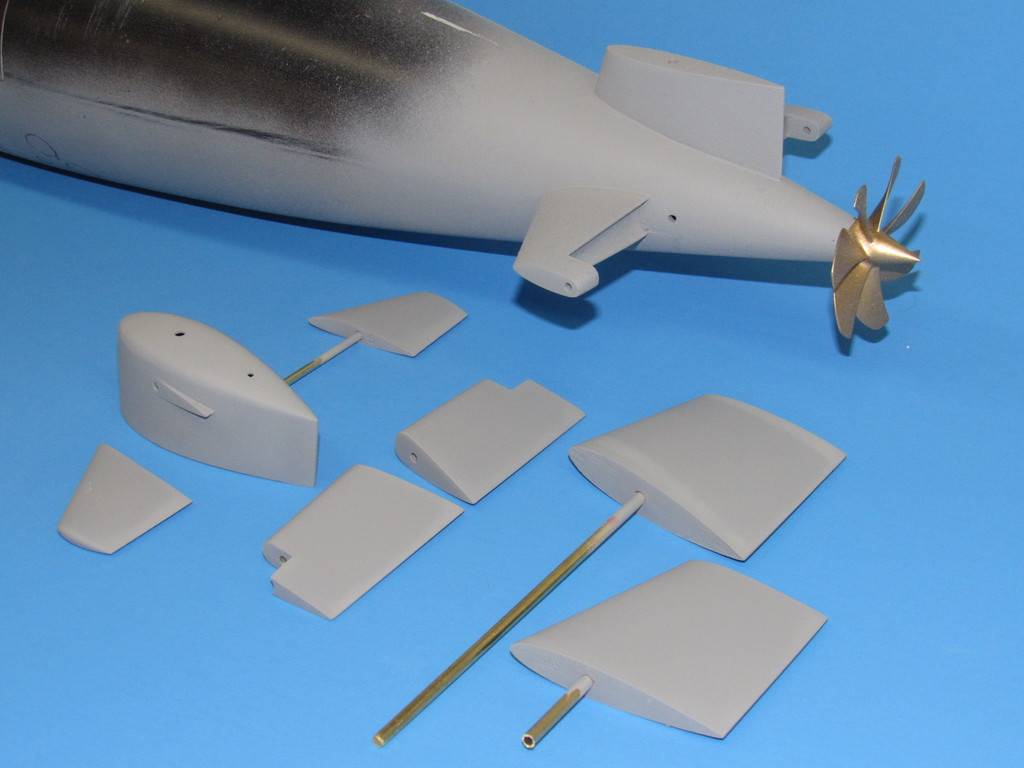
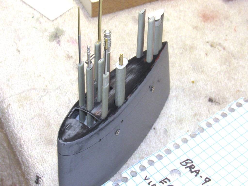
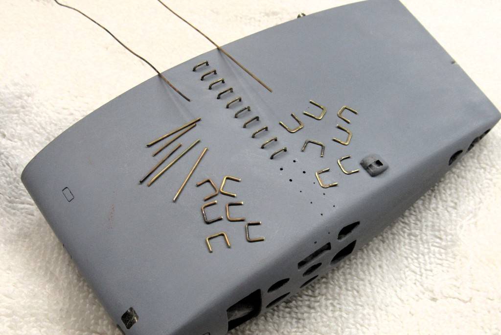
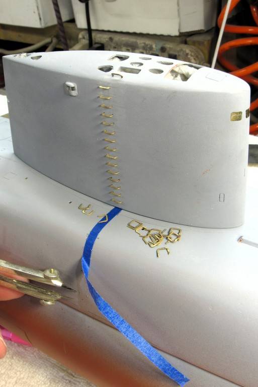
This big model demanded all the little details I could apply to it. That included the many ladder rungs that ran up from the waterline to the top of the sail. It's the small stuff that turns a toy into a proper display piece.
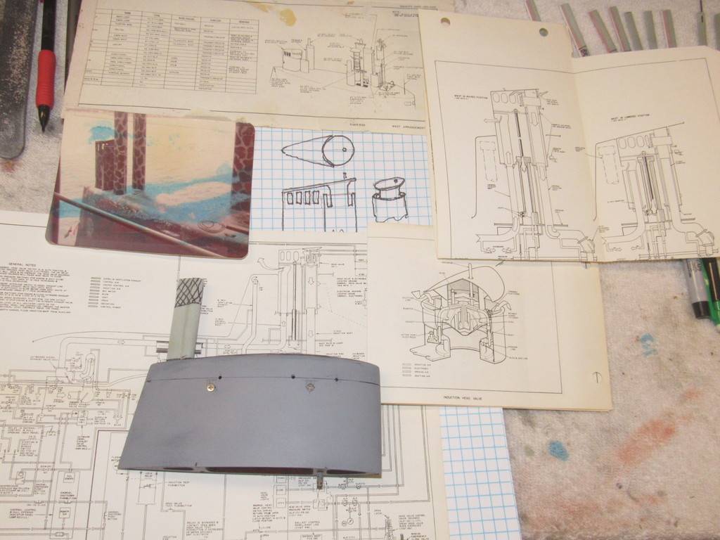
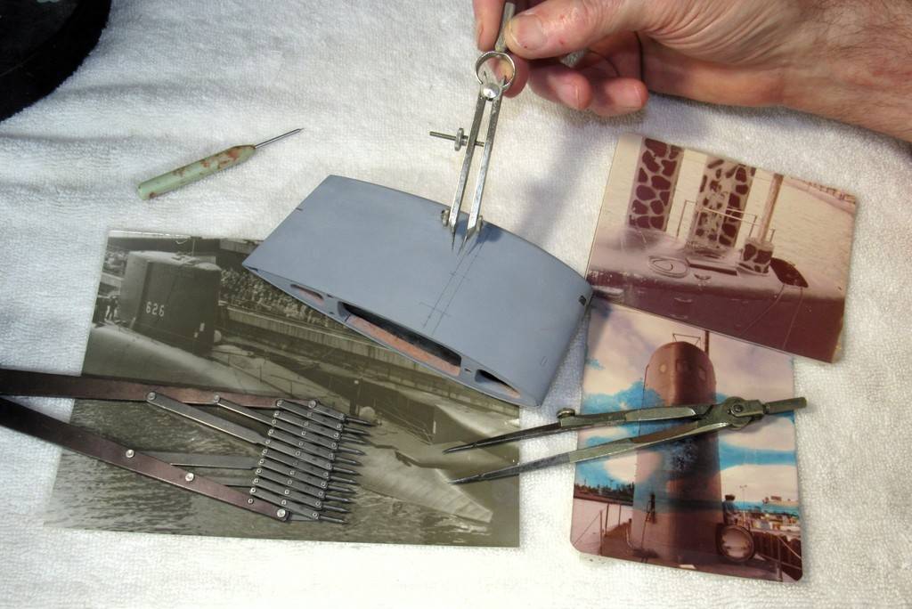
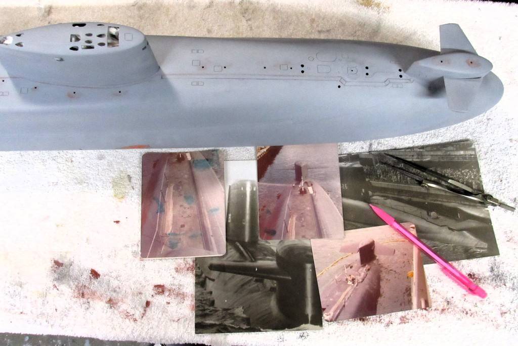
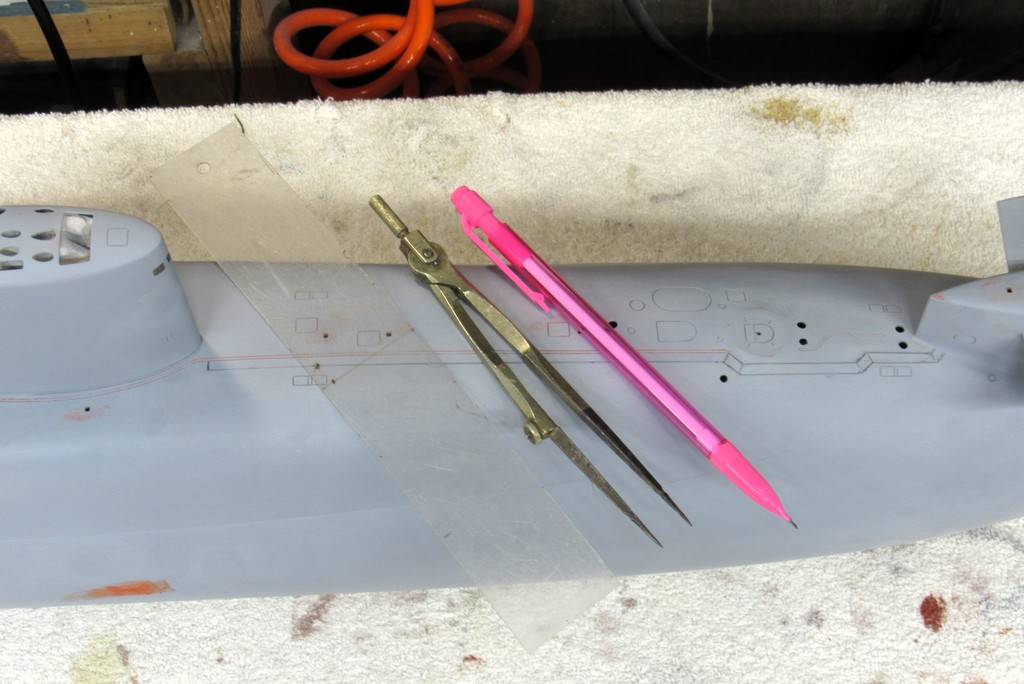
Some of the documentation and layout tools used to position the ladder rung stem holes. The two rather faded color photos were taken by me of the boat during one of her re-fits in Guam, as we worked the boat up for another patrol.
... Hell, I snapped those over a half-century ago. Sobering.
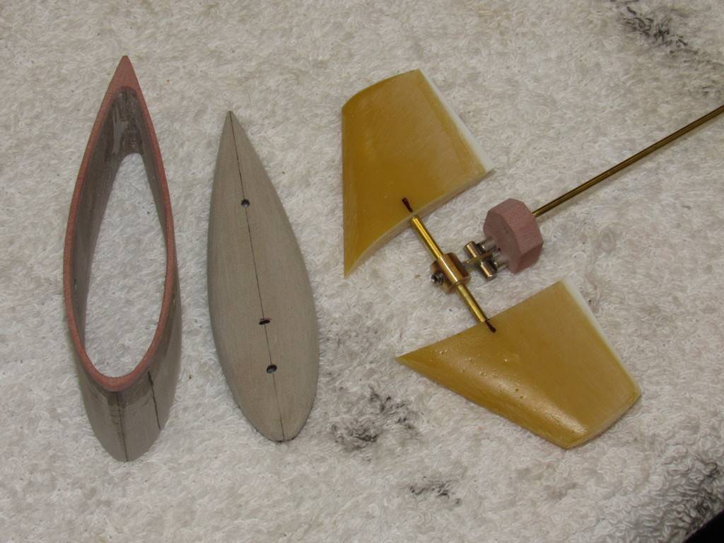
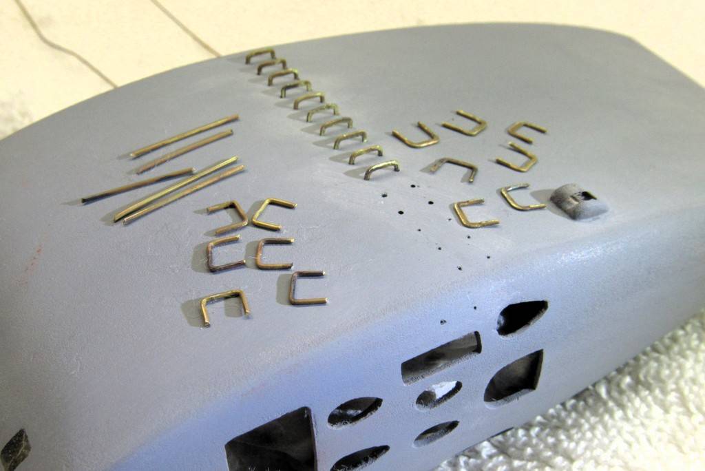
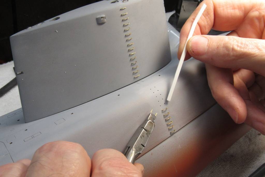
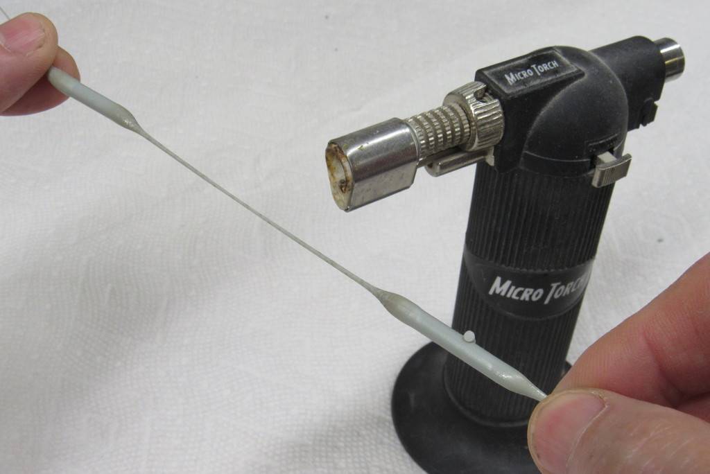
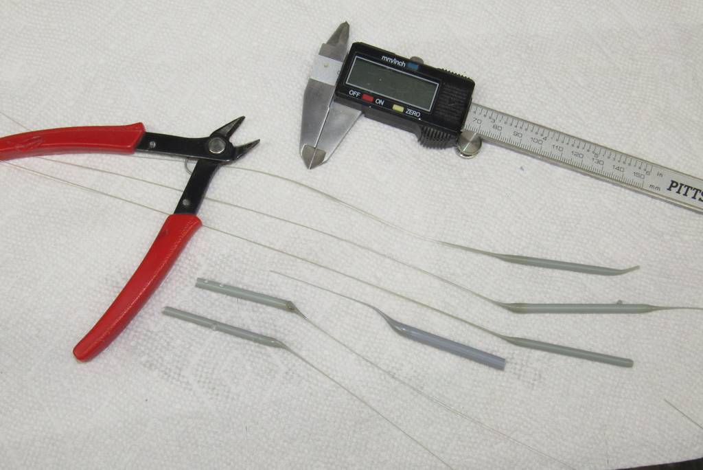
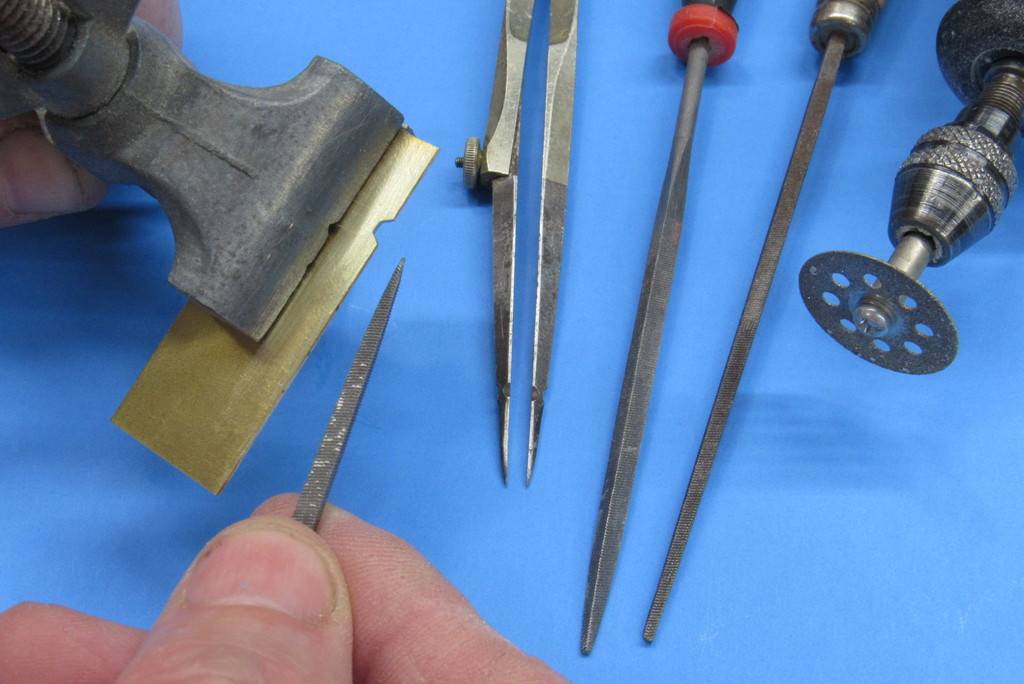
To the left are raw ladder rung blanks, still in the round. To the right are properly flattened ladder rungs ready for installation onto the model. These were made from annealed .020” diameter K&S brass wire.
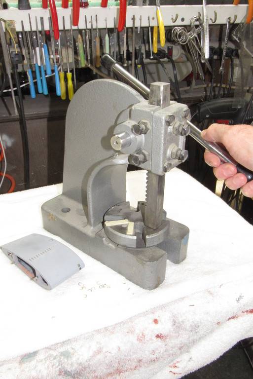
A hand-press was used to flatten the annealed brass rung blanks.
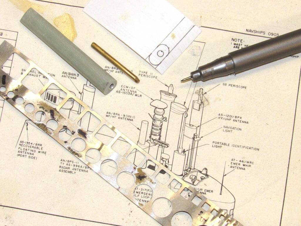
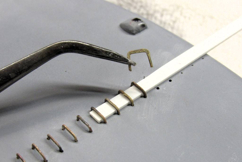
This length of plastic strip was used to set, exactly, the height of the rungs off the surface of the models sail and superstructure.
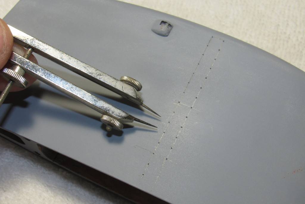
The drafting compass insured equal vertical spacing between rungs and the temporary strip of masking tape insured correct horizontal spacing between the holes that would secure the stems of each ladder rung.
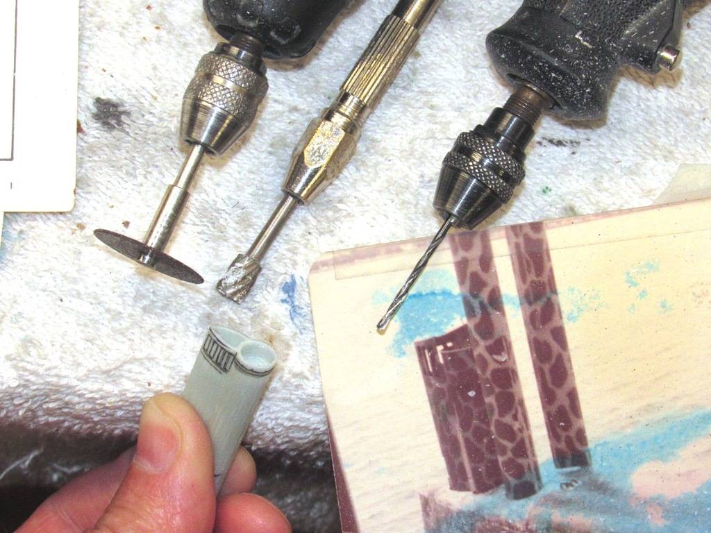
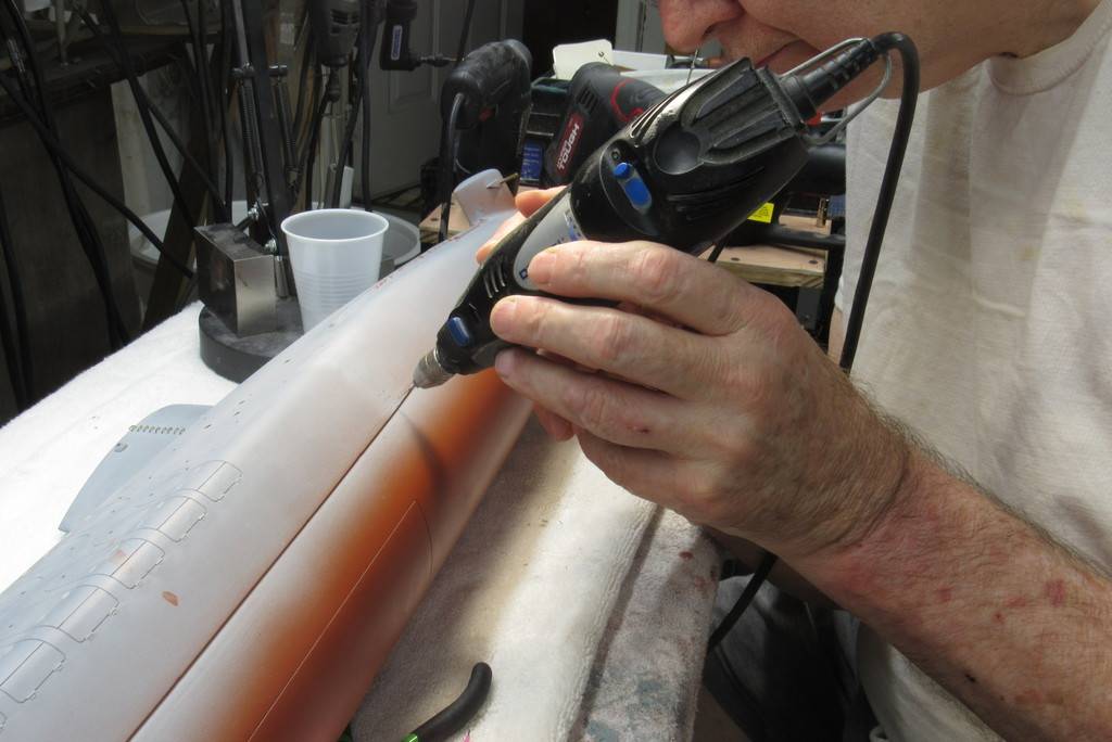
The moto-tool equipped with a .020” diameter bit drilling holes that will accommodate, via an interferrence fit, the stems of the ladder rungs.
Note the use of a modified set of pliers here – they started life as a common needle-nose type but were truncated and the tips ground back to better hold a rung yet not make contact with adjacent rungs as a rung was installed/removed from the sail and superstructure.
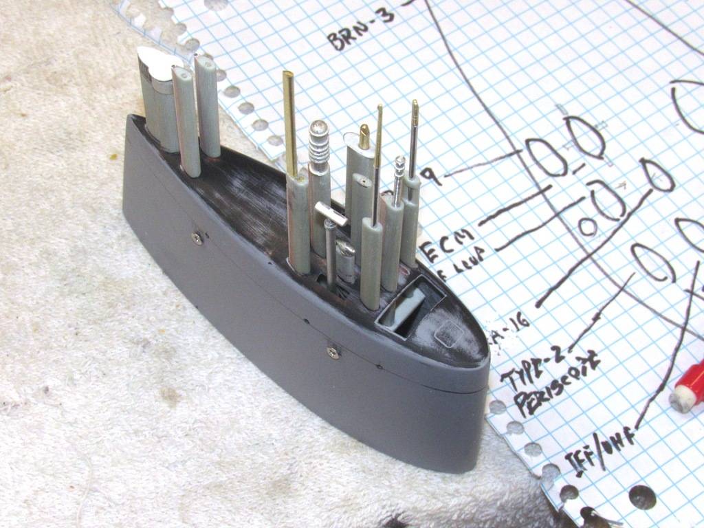
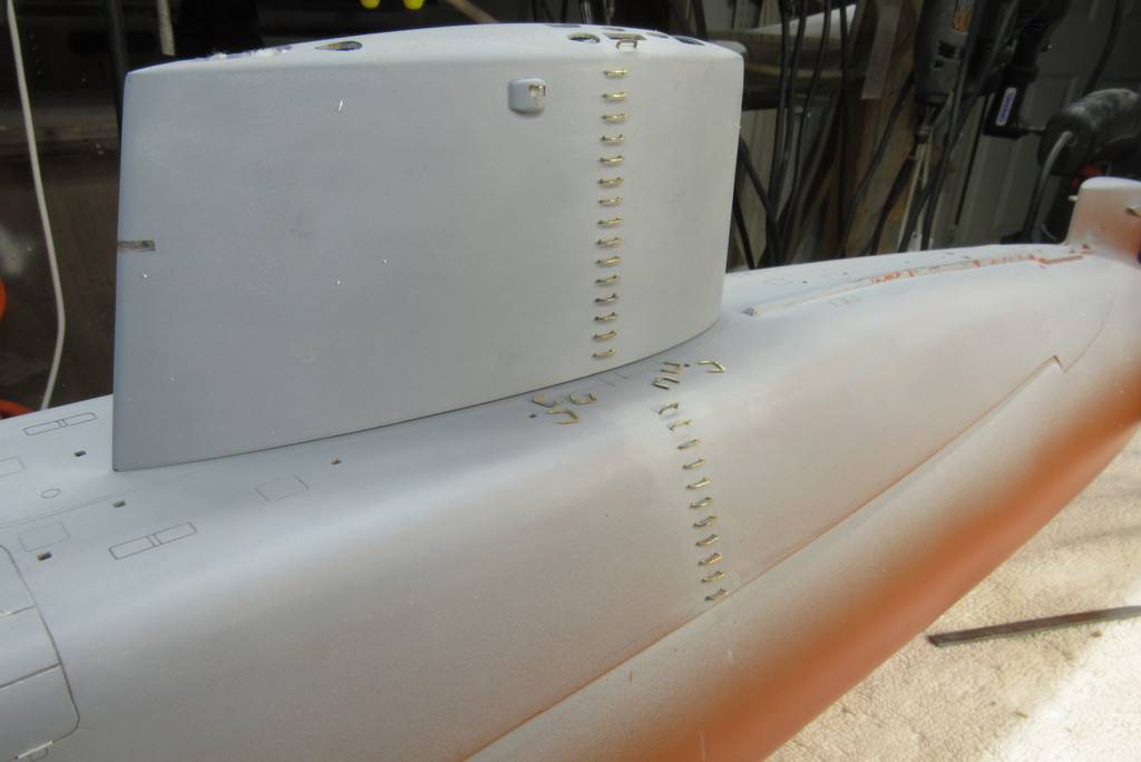
All of the ladder rungs are tight friction fits to the sail and superstructure, so no glue is required to retain them in place. This permits me to now remove the rungs and carry on with the painting and weathering of the model without the rungs getting in the way. The rungs will be painted separately and installed before the final flattened clear-coat goes down.
David, You looking for the Scot or the Ayn Rand character? ;)
Could be, Bill.
But what really blows up my skirt is the purity of purpose, and sense of self of her Howard Roark, and Hank Rearden characters. True representatives of the best characteristics of man; virtues that could only be grown in the America of years past (not today). Today, the great American experiment has failed. Socialism has won (the tool of our defeat: regulations and no term limits).
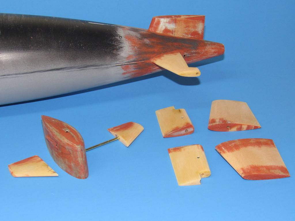
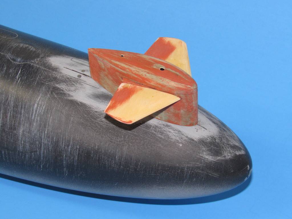
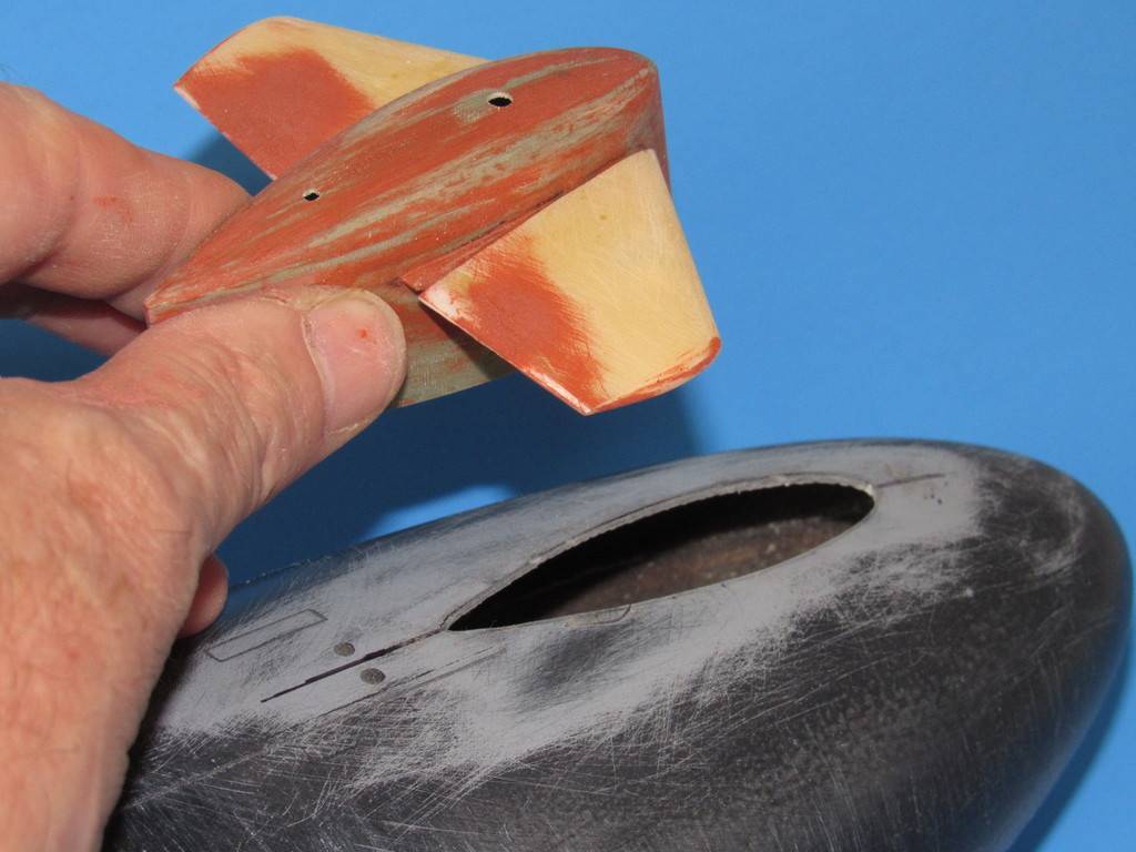
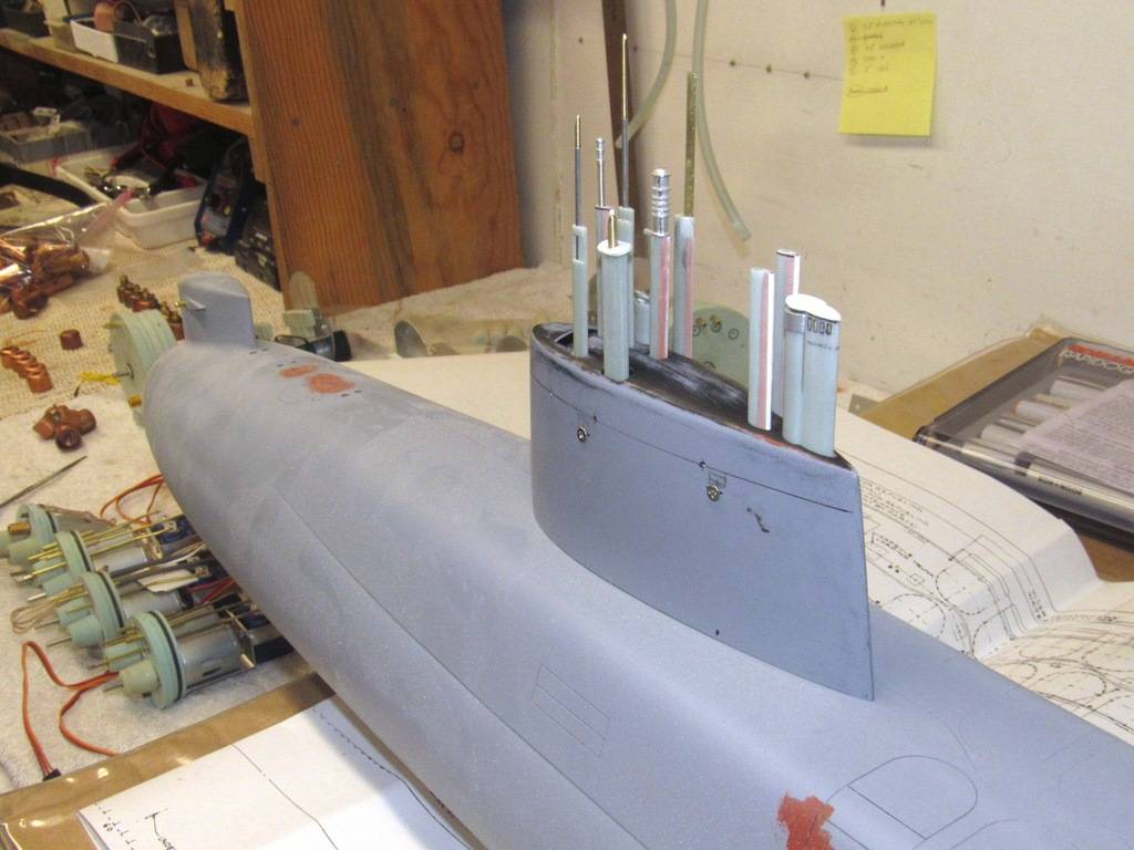
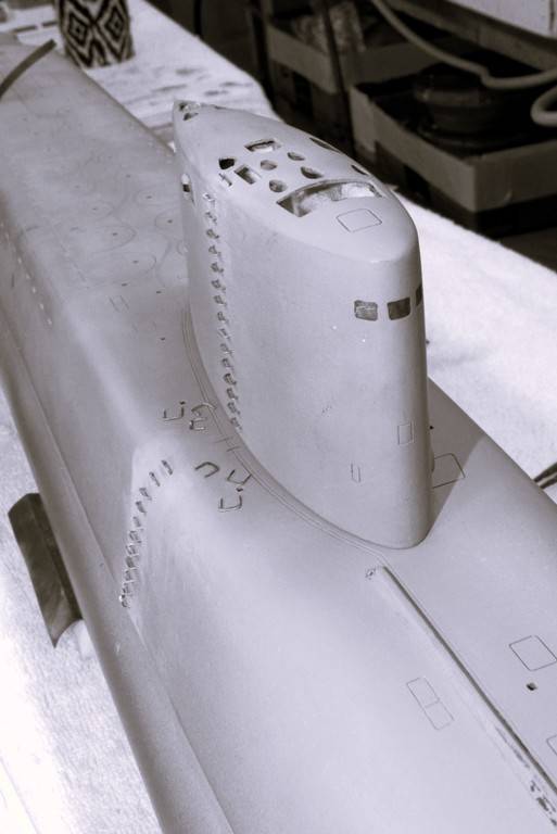
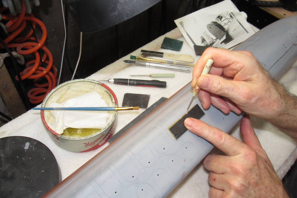
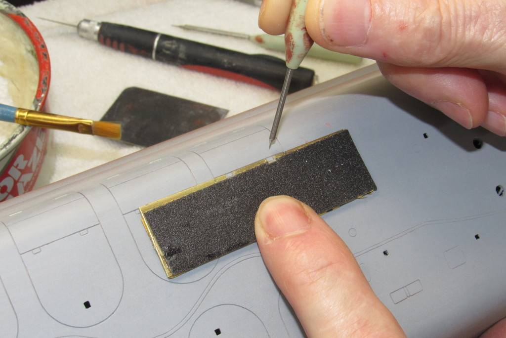
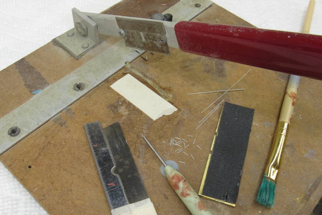
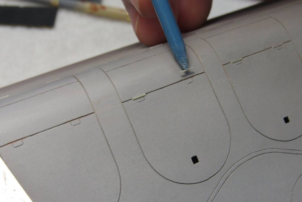
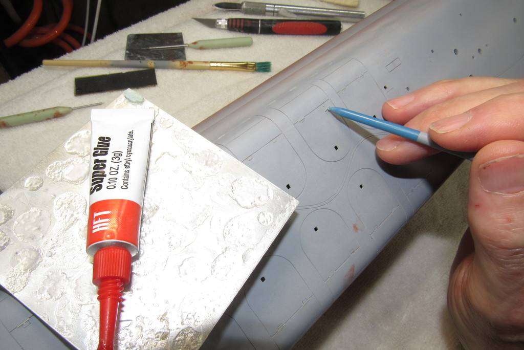
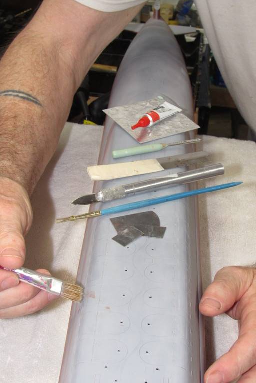
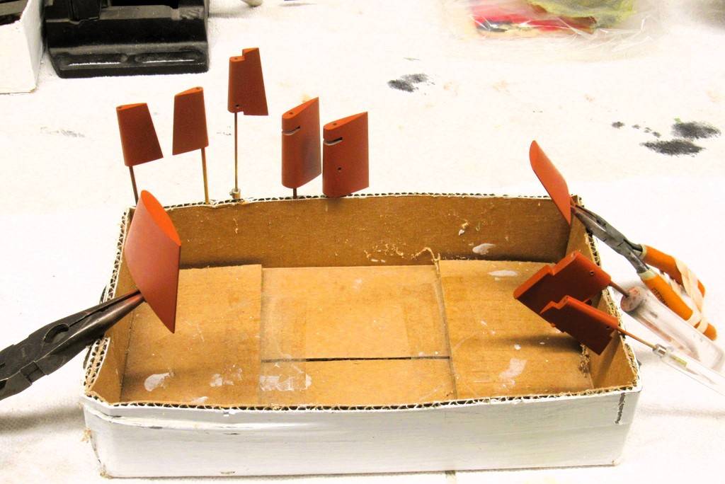
It's often the 'little things' that makes an otherwise fair model to become an interesting and appreciated display. Little things like the projecting hinge pins employed to permit travel of the three-piece missile tube muzzle hatch fairings.
Missile tube fairing hatch hinge securing brackets were represented by engraved rectangular shapes scribed in with the aid of this purpose built stencil.
Stretching sprue to derive the correct diameter, round of section fairing hinges.
I found that the ideal hinge diameter was .015”. So, with the aid of a micrometer I found those lengths of stretched sprue that fit the bill and cut them away for later chopping to length.
A very useful tool for slicing thin, soft plastic sheet and extruded shapes is this commercially available 'chopper'. Here I'm using it to cut to length stretched sprue missile tube fairing hinges. Uniformity of length is assured through the use of a masking-tape fence.
I used a bit of spit to hold a 'hinge' piece at the pointy end of a paint-brush handle. Just enough stick to permit me to transfer a hinge from the chopper to the engraved line of a missile tube hatch fairing engraved line.
A very small drop of CA was placed on the engraved line and a hinge placed into position and pressed down hard with a finger for about five-seconds – long enough for the glue to take hold.
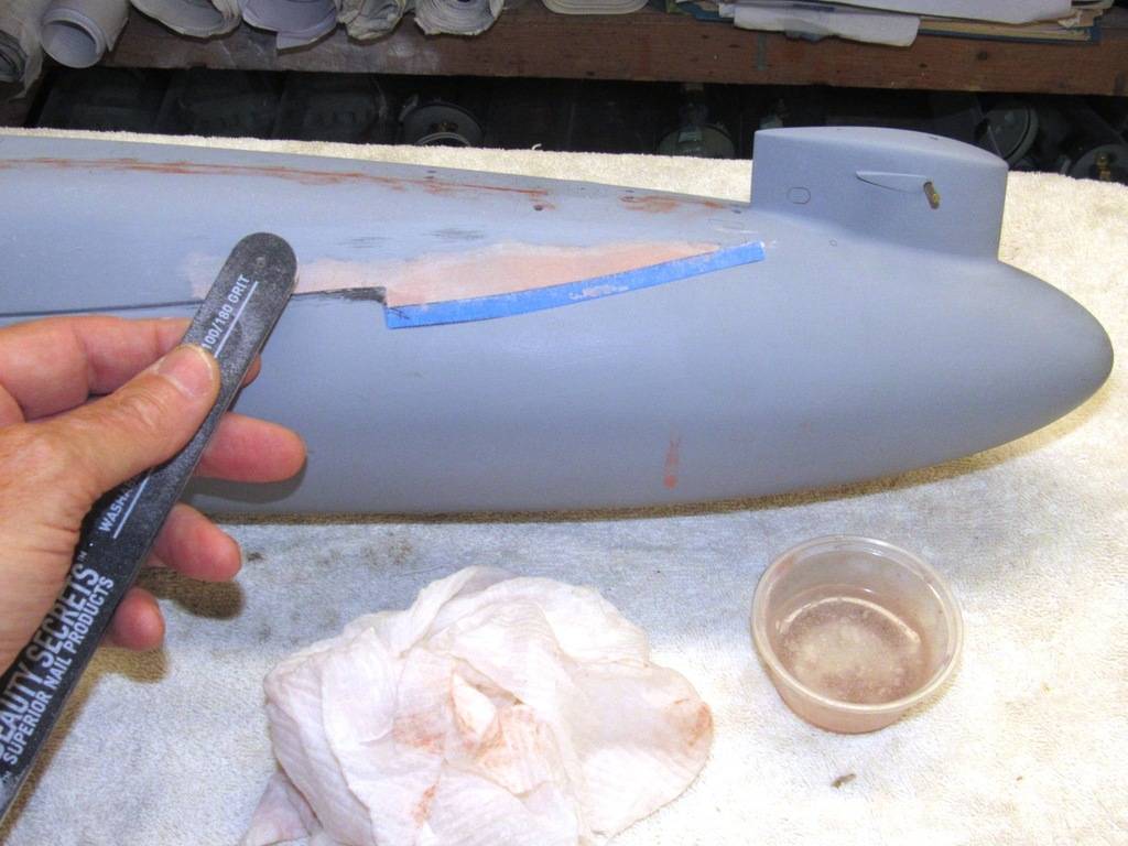
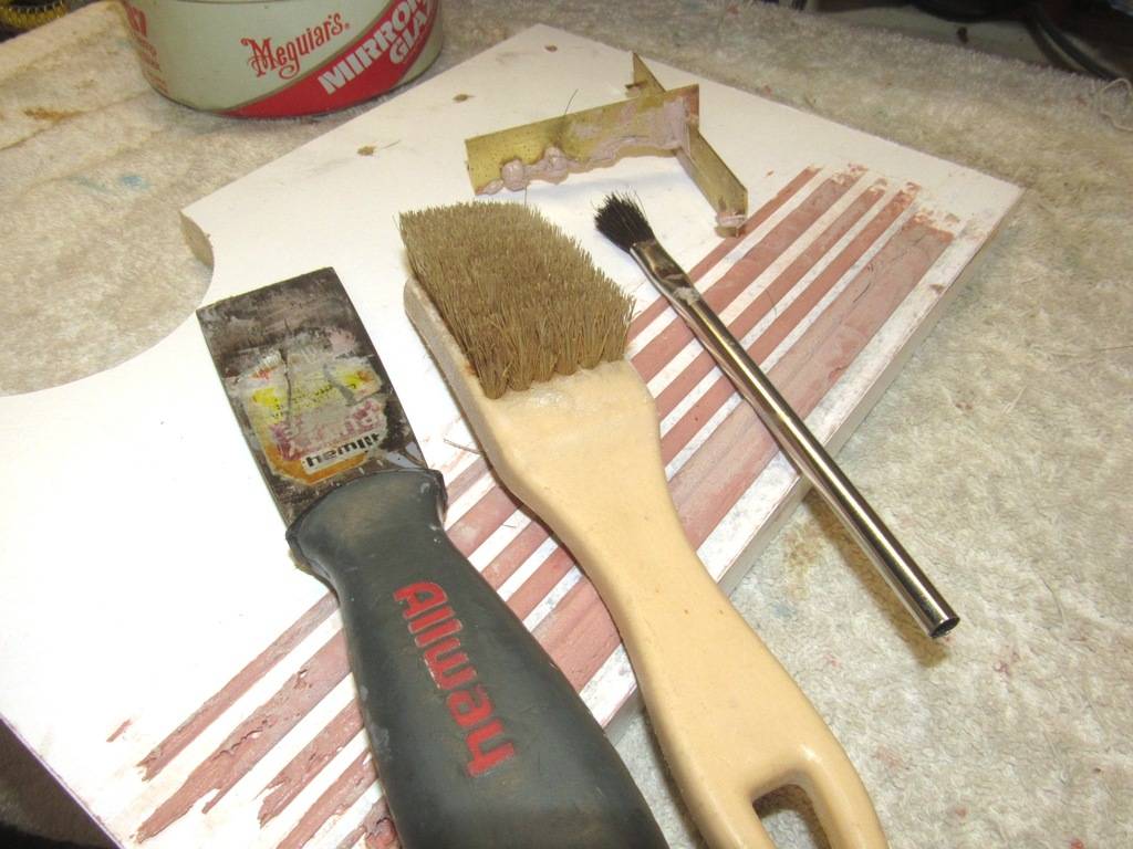
Careful blade scraping and sanding with #600 around the slightly raised hinges cleaned up any excess glue. Here I'm chasing out sanding dust from the engravings with a stiff paint-brush.
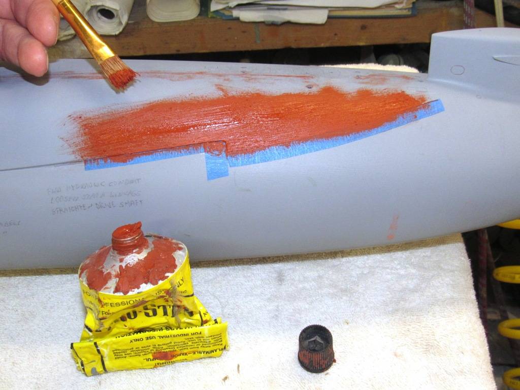
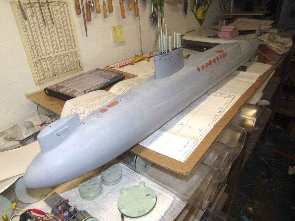
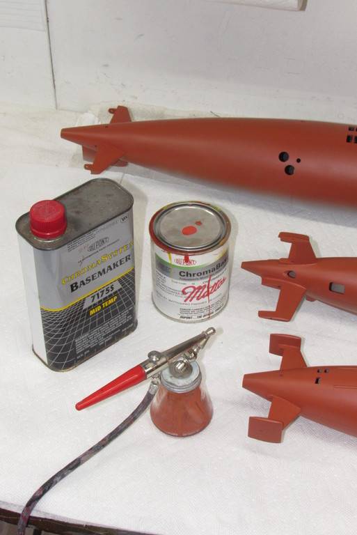
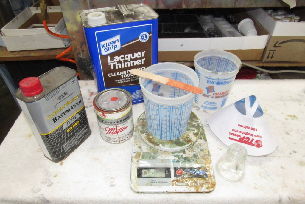
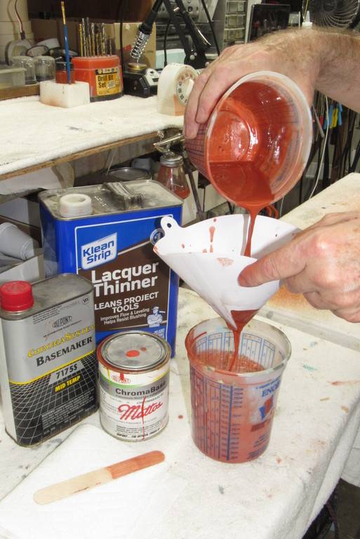
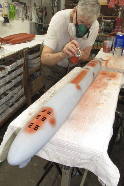
Time to splatter some paint on these three suckers! The paint chemistry is my old friend: two-part, polyurethane DuPont ChromaColor. This automotive paint is tough, quick curing and can be reduced significantly without losing its opacity, which makes shooting it with small air-guns like my trusty Paasche H-model, single-action a very easy proposition.
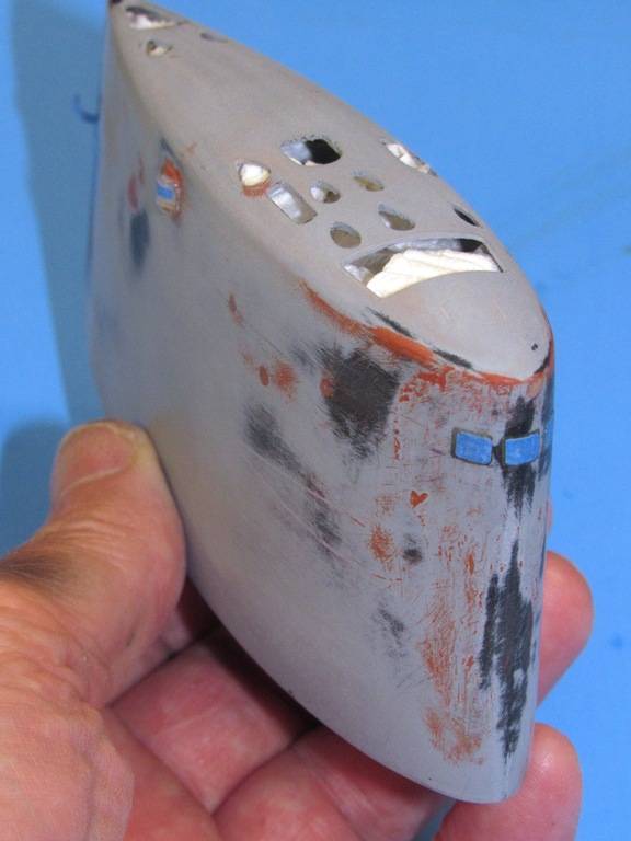
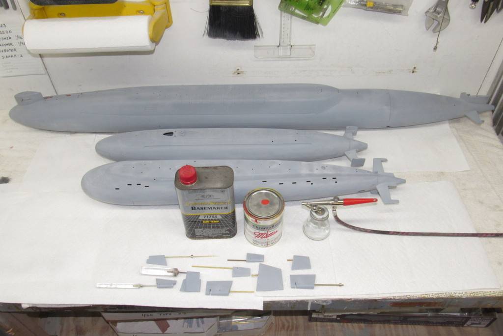
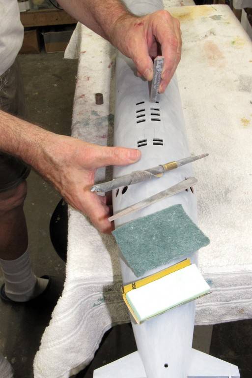
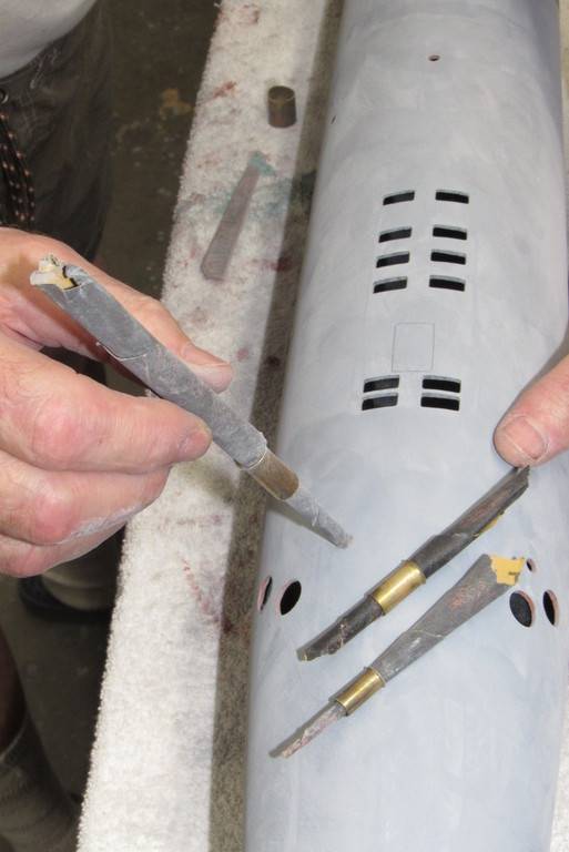
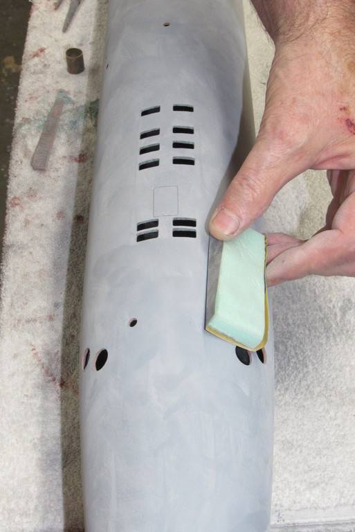
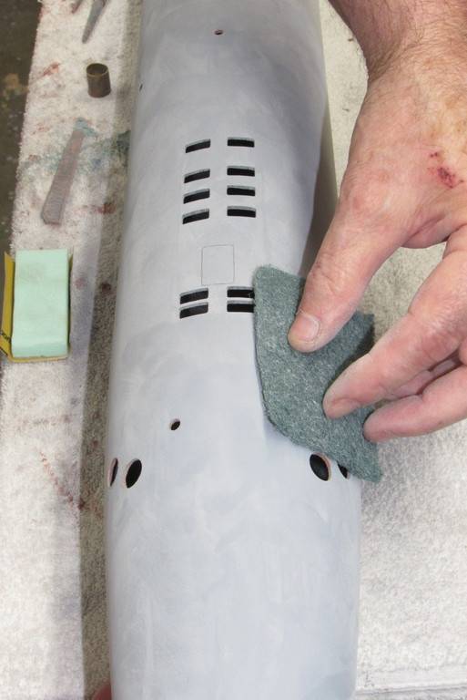
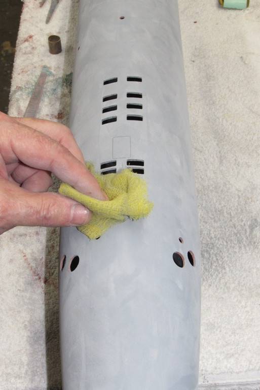
The 1/96 WEBSTER, KILO, and BLUEBACK – all at this point in their final primer gray – had their hulls and appendages given a final dry sanding with #600 grit abrasive; a polishing with an abrasive pad; blown-down to get any sanding dust trapped into the engravings; and everything wiped with a tack-cloth to remove the last little bits of sanding dust from the surfaces to be painted.
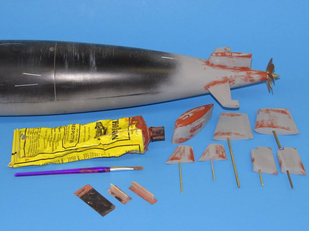
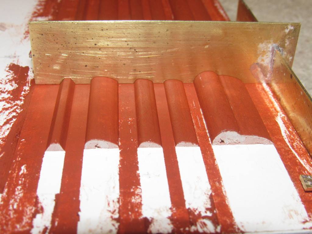
The first color to go down was anti-fouling red, applied to all hull and appendages that would either be below center line, or below water line. The demarcation line between red and black would be center line on the WEBSTER and KILO, and waterline on the BLUEBACK.
Who is John Galt indeed? Some of us know David. Great work as always and I'm so glad to see it. I nearly had to leave the planet recently but thanks to good doctors and medical science I have a stay of execution.
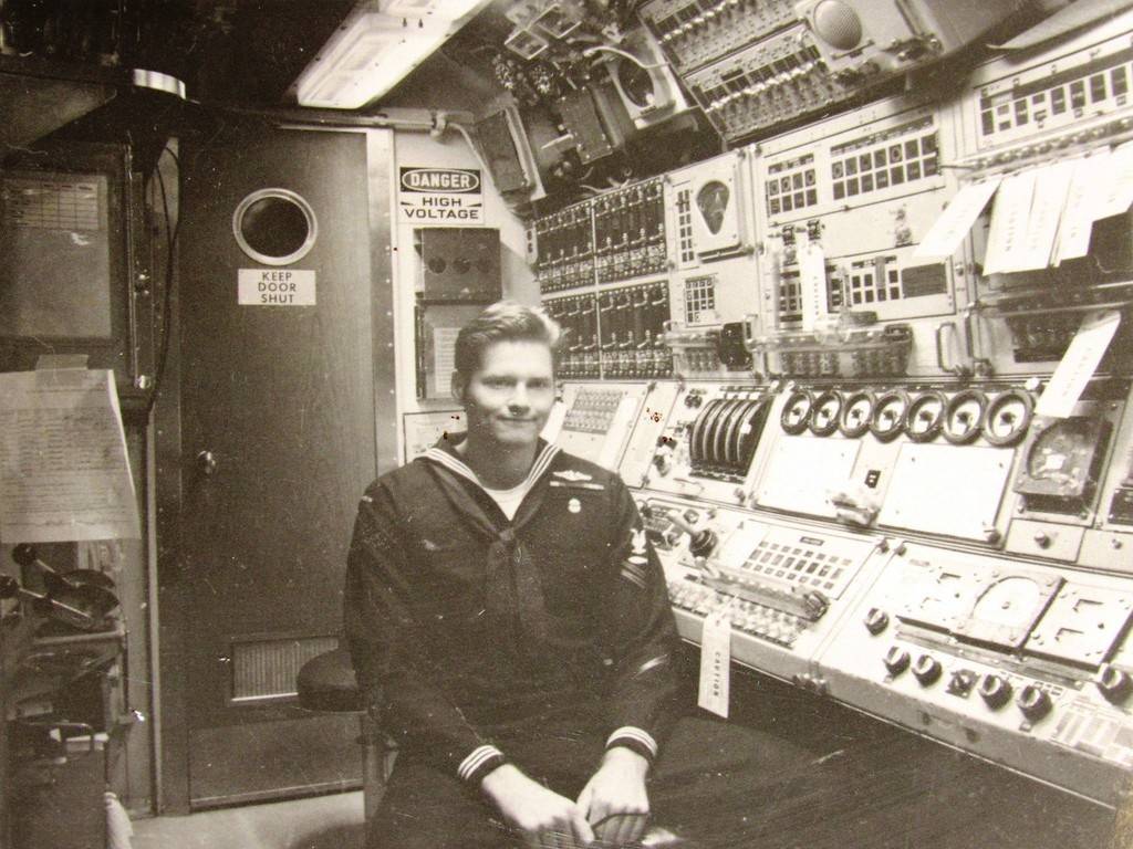
I remember seeing a photo of those “bow planes” but I never realized they were on the Daniel Webster. I had an interesting relationship with that boat. The first time I went to school I attended Daniel Webster College in Nashua, NH. After I gloriously failed out of that fine institution, I joined the top 5% of college dropouts and attended Nuke Power School, spending 6-months on MTS-626 EX-DANIEL WEBSTER learning how to operate a nuclear reactor.
I understand they turned the bow compartment/torpedo room into a classroom when they converted the pig-fish to a trainer. The venerable S5W plant -- one of the finest pieces of engineering on this planet.
I remember seeing a photo of those “bow planes” but I never realized they were on the Daniel Webster. I had an interesting relationship with that boat. The first time I went to school I attended Daniel Webster College in Nashua, NH. After I gloriously failed out of that fine institution, I joined the top 5% of college dropouts and attended Nuke Power School, spending 6-months on MTS-626 EX-DANIEL WEBSTER learning how to operate a nuclear reactor.
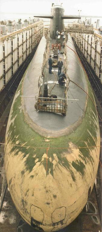
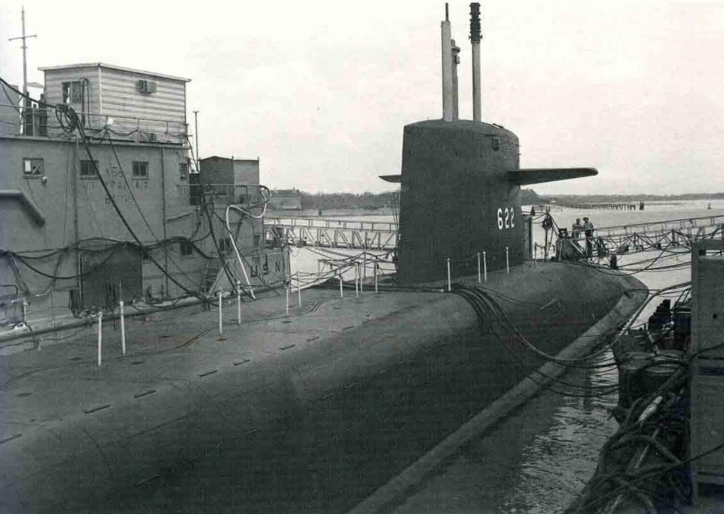
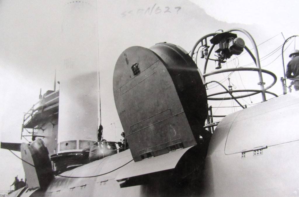
Take your basic Mark-1, Mod-0 LAFAETTE class SSBN submarine, and move the sail planes to the bow, and you get the one-off boat of the class, the USS DANIEL WEBSTER.
A laudable effort: putting the planes forward greatly improved the ability of the ship control party to seek, obtain, and stay put on assigned depth. However, by placing the ever clanking ram, squeaking operating shaft bearings, and linkage back-lash – put all those noise sources so close to the boats bow mounted sonar arrays and you've taken a step too far. The kind of stuff that makes the sonar gang nuts.
The WEBSTER was a joy to drive in depth, but the noise those planes produced rendered the passive sonar gear near useless when running shallow in any sea-state other than glass smooth. The WEBSTER finished her career with the planes placed on the sail. Where they belong. The grand experiment was over. Boomers don't have to be agile, but they do have to be quiet.
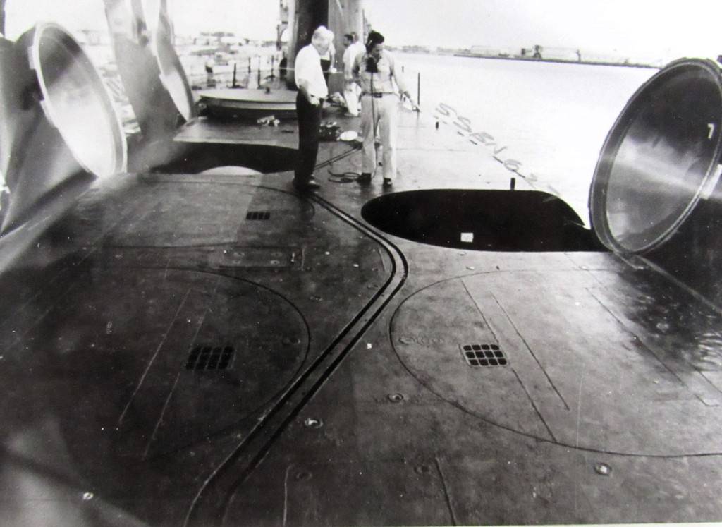
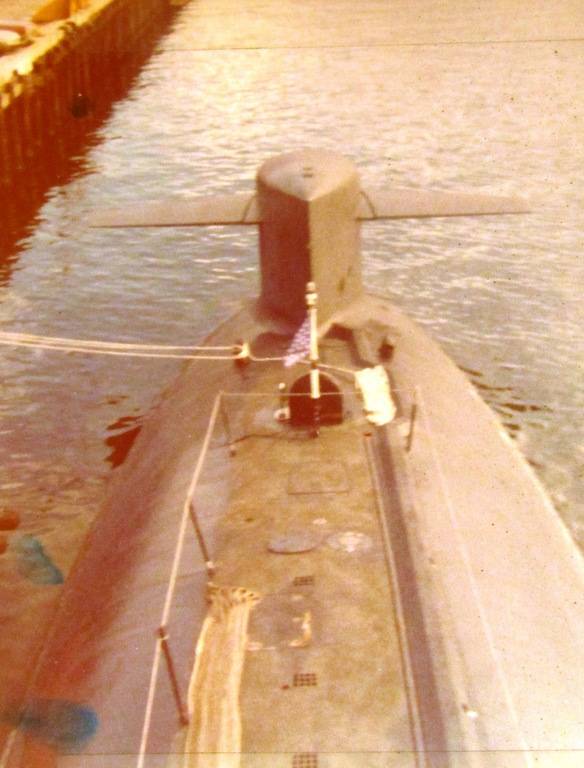
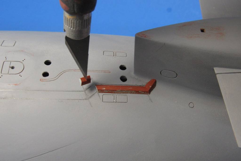
The hydraulic lines to the bow planes ram ran on the starboard side of the deck and were covered by an armored conduit. That conduit, which ran a rather twisting path along the deck in order to clear cleats, safety track, and main ballast tank vents – had a section of a truncated cone; sloping sides, with a flat top. This of course was a unique feature of the boat when she sported bow planes. A feature that had to be represented on my 1/96 model of this most iconic SSBN.
I snapped this shot from the bridge of the WEBSTER while we were at Pearl, getting ready for our canal crossing to Groton for a major yard period and missile upgrade, from Polaris A-3 to Poseidon.
Study of my documentation gave me a pretty accurate layout of the conduit. After a few poor attempts, I finally penciled onto the models hull the path of the conduit from just off the sails leading edge to the starboard side of the bow plane fairing (often referred to as the 'wart').
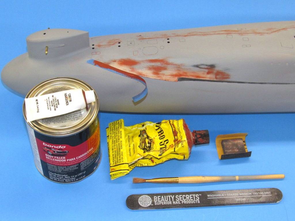
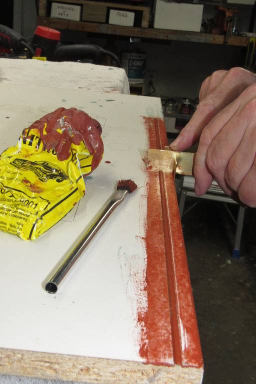
As no commercially available lengths of plastic shape had the geometry or dimensions needed, I elected to screed out a length of properly sectioned conduit from Bondo.
Linear screeding is simple: Plop some catalyzed Bondo onto a waxed flat board and run a properly shaped die across it linearly.
Here you see the screeded periscope and antenna fairings formed using this process. To the left is my initial attempt at creating the bow plane hydraulic line conduit but found that it was much too wide and tall of section to work at 1/96 scale. Dummy! But this shot does illustrate the sectional shape of the conduit.
As one of my Junior High School shop teachers was fond of saying: “measure twice... cut once. Moron's!”
Here I'm giving shape to the die of the second conduit forming attempt.
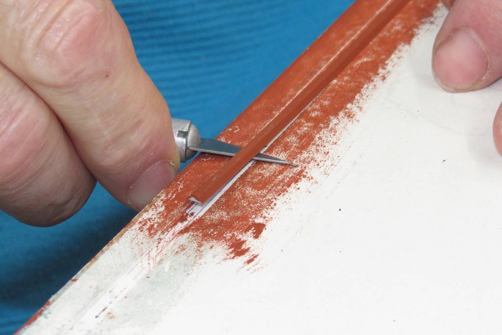
Here I've screeded out a one-foot length of Bondo conduit. Took about five passes, but the work went quickly.
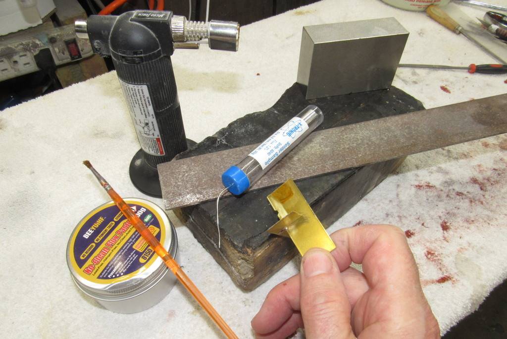
The final pass was a coating of Nitro-Stan air-dry touch-up putty.
I let the work cure and dry overnight and the next morning lifted the work off the board.
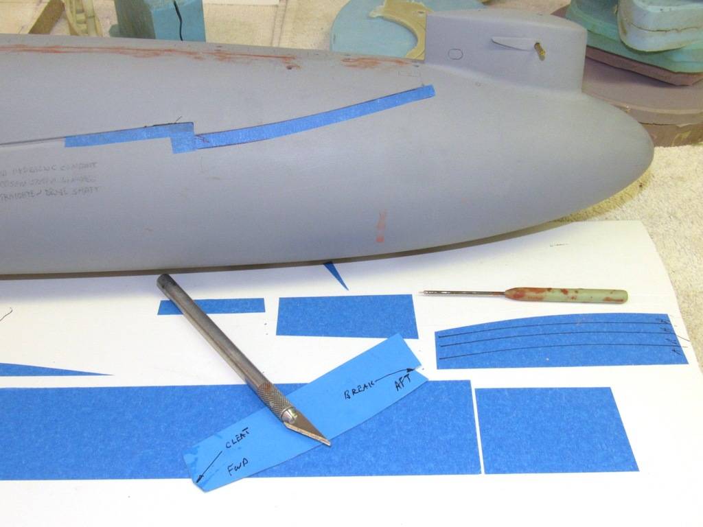
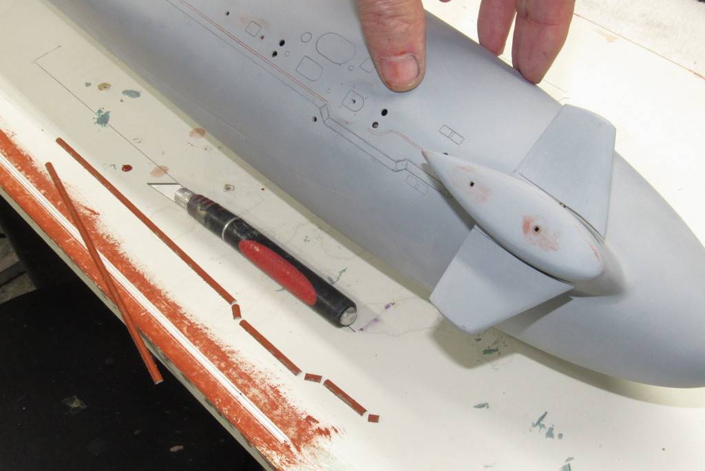
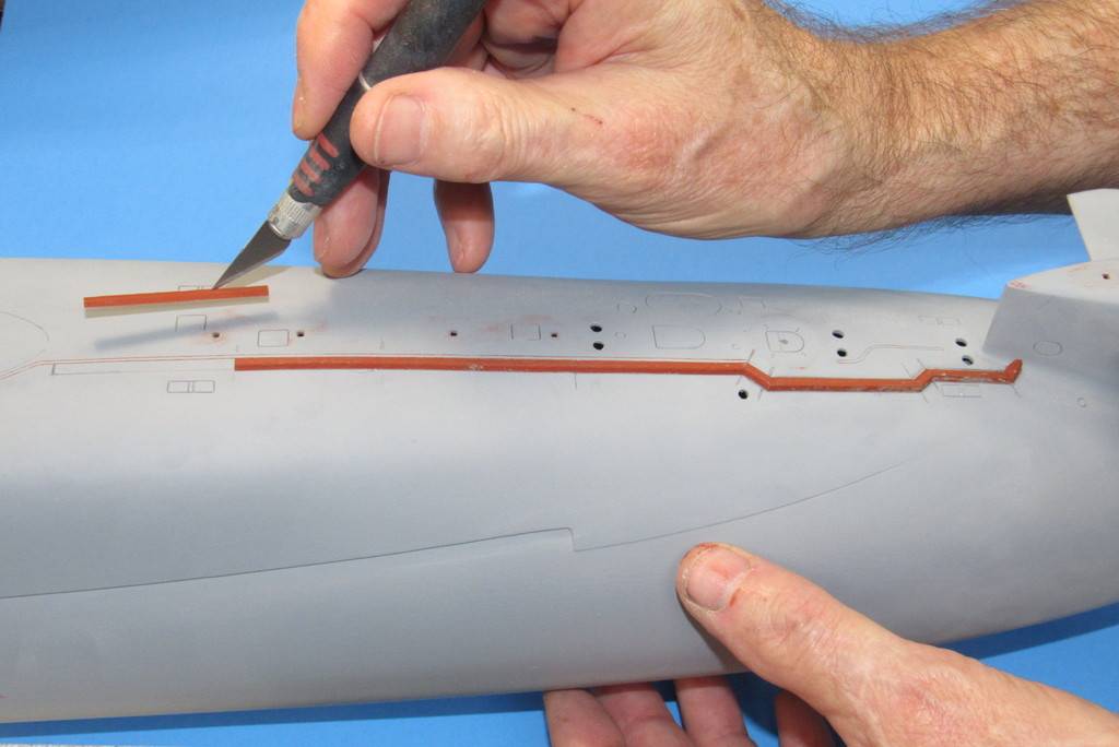
The long length of conduit blank in hand I lofted the breaks off the penciled model and started to cut things to proper length and angle.
… and glued each section of conduit in place with the aid of thin formula CA adhesive.


Leave a comment: