
-
Scott,
I cannot view the video. It says the video is unavailable.
peace,
tomLeave a comment:
-
-
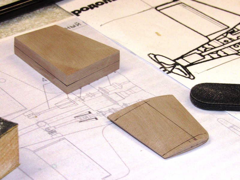
What would become the masters for the upper and lower vertical stabilizer-rudders started out as 40 lb. RenShape blanks cut to the outlines of those structures. The rudder portion of the two assemblies would be cut away from the stabilizer only after all profile and section shaping had been accomplished. A virtue of the relatively soft RenShape is the ease at which it can be sawed and cut with a knife – reducing the kerf lost as rudders were separated from stabilizers.
Note the two closely spaced radial lines at the stern of the upper hull. These denoted the saw location as I removed this piece and later bonded it atop the lower hulls stern.
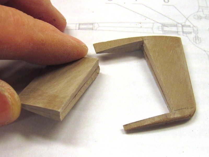
Each blank was split on the band saw, sanded smooth and the adjoining faces darkened with a black marker pen, then glued back together with CA adhesive. This produced a sharp, dark line at all edges of the blank that served as a visual indication of the centrally running datum plane as I cut each vertical stabilizer-rudder master to its proper ‘airfoil’ shape. You can make out the outlines of the datum plane on the upper stabilizer master blank as well as the datum plane outline on the fully contoured lower stabilizer-rudder master. The clearly observable centerline assists greatly in assuring symmetry as I hack and slash with moto-tool, file, and sanding-block.
The shapped lower stabilizer-rudder has been pencil marked indicating where I would use saw and knife to liberate the rudder from the stabilizer.
And here, with surprisingly little effort exerted, is the removed rudder and stabilizer. The vertical break achieved with a new #11 X-Acto blade, and the two horizontal cuts done with a very thin bladed razor-saw. To forestall the possibility of breaking the stabilizer trailing edge portions at the top and bottom I first coated the master with thin formula CA. The CA penetrates the porous RenShape and greatly strengthens it. The added strength making it stout enough to resist breakage as a result of the slight shear forces generated by the razor-saw.
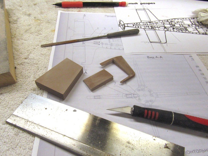
The Russians don’t go in for ‘balanced’ control surfaces on their submarines – without exception they place the control surfaces center of rotation right at the leading edge. Such is the case with the ALFA’s stern planes and rudders. With the rudder now removed I’ll have to add a strip of RenShape to its leading edge and round that into a cylindrical shape that in turn will nest into a concave recess that will be ground into the stabilizer.
Eventually I will pass a length of 1/16” brass rod through holes drilled through the stabilizer and rudder, that rod becoming the rudders operating shaft.
Today I’ll give the upper stabilizer-rudder blank the same treatment and then work up the fillet between the root of each assembly and the hull.
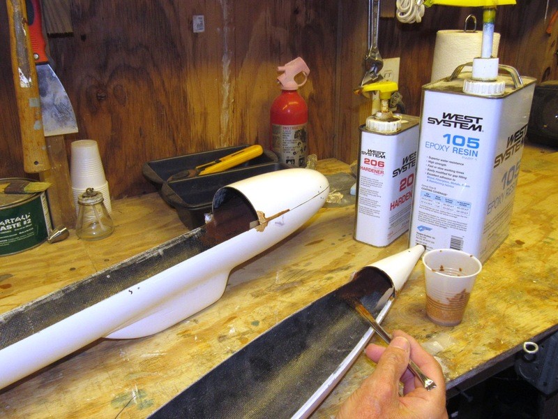
When cutting into a fiberglass reinforced structure, such as your typical glass reinforced plastic (GRP) r/c submarine hull, keep in mind that your cutting tool either has to be tougher than glass or at least of an ablative type that will cut, fail, and be consumed as it grinds through the glass.
Diamond is tougher than glass, so if you can identify a diamond cut-off wheel thin enough to keep the kerf less than 1/16” then go with that. If not, do your cutting with a thin, un-reinforced carbide cut-off wheel. Both tools swung with your typical MK-1 Mode-0 Dremel Moto-tool. Eye and lung protection a must during this dusty operation!
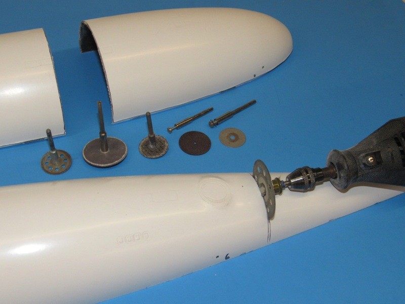
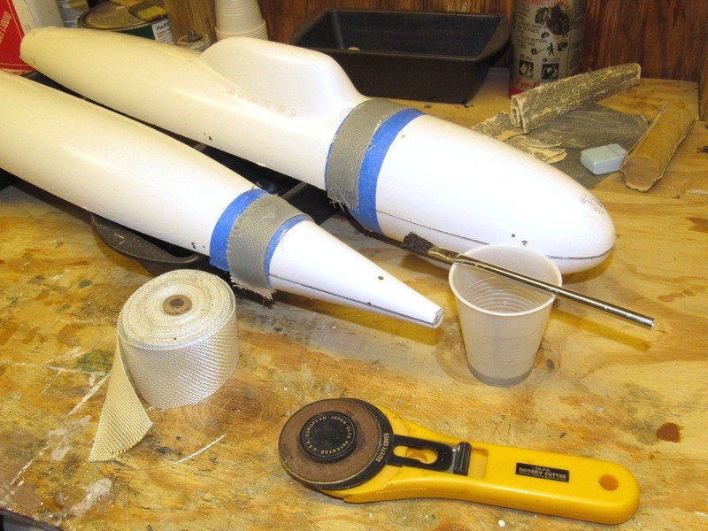
The removal of the upper hull stern and lower hull bow is done to produce the Z-cut between the assembled hull halves. The stern section bonded to the lower hull, and the bow section bonded to the upper hull.
Once the pieces were cut away they were cleaned up and tack-glued to their respective hull halves with CA.
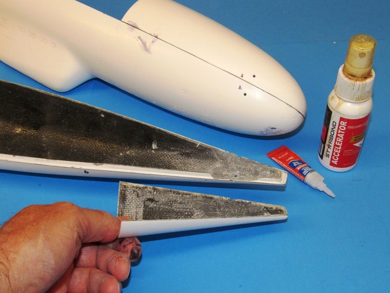
Glass tape, saturated with slow-cure epoxy laminating resin, applied inboard, bonded the bow and stern pieces permanently in place.
A radial flange has to be provided at each end of the hull haves. To capture the compound curve at these points I simply laid down some glass strips over the hull and saturate the work with laminating resin. Once cured hard they are removed, cleaned up and installed within the hull so each project a bit past the radial cut, forming a lip, or foundation, upon which the other hull half radial edge can seat.
To keep the work from sticking to the hulls I first laid down a strip of masking tape, over which was applied a layer of mold-release wax.
Leave a comment:
-
-
-
-
-
After Greg Sharpe sold that kit to Matt Thor, Thor asked me to make up and sell him appendage kits to compliment the kit. You may have gotten some of my 1/72 ALFA appendages from him? Anyway …. very nice job on that model, Scott, and a pretty fair paint job and weathering too.
Hey, if you want new parts for that 1/72 ALFA, let me know, I have all the tooling -- just say the word, NOVEMBER-boy. And if you are still looking to fatten your ALFA folder, get this book!
DavidLeave a comment:
-
The appendages came from an after market supplier, and failing memory procludes me from saying who that was. I made the fore planes, the creeper props and the dunce cap for the prop myself - I think I stole the prop from you. I was realy referring to how nice your upgrades looked and lamenting the fact that my Alfa is now slightly inferior. Also envious of all that documentation!Leave a comment:
-
The deal I have with Lee is a non-exclusive. I provide him with the tools, he takes it from there.
I reserve the right to incorporate the masters into any future 1/96 ALFA project I choose, and may do so in the near future.
Nautilus Drydocks is my sole employer -- I won't sell to a third-party. However, George, you're a get-things-done sort of guy; how about I send you a set of appendages and what-nots when I'm done, and you finally finish that long suffering ALFA of yours? Pay only postage; sing my praises; and post your work to this site, and we'll be even-steven. You and Eric can race each other to the finish line.
Deal?
DavidLeave a comment:
-
Hello, Thanks for posting this project. Can I ask to make sure, you are going to make the upgrades for the Alpha BUT will you also sell them OR do we have to go through Scale Ship yard for them? I have a VERY OLD Alpha without the indexing lip that for sure I would get your upgraded kit, once available.
Please let us know.
Thanks
George
Leave a comment:
-
-
Oh, this looks so good! Where were you when I was building my 1/96 Alfa?
Leave a comment:
-
A marking-board was made from some shelving. Its purpose to hold a hull half securely while I marked off specific positions, such as operating shafts, Z-cut points for the bow and stern, and the desired location of the models center of gravity and center of buoyancy.
Radial lines would be laid down with the assistance of a pen loaded surface gauge running along the vertical face of a fence screwed to the marking-board and its face oriented perpendicular to the hulls longitudinal axis.
Where the tail-cone and bow pieces would be removed from their respective hull halves were indicated by two closely spaced radial lines put down with the pen loaded surface-gauge (waterline marking tool, if you will). The space between these closely spaced lines represents kerf loss. The thickness of the kerf established, I then knew how much material has to be built up at the radial edges once the re-attached stern and bow pieces were bonded to the opposed hull half.
The radial lines are laid down with a pen loaded surface-gauge riding along a vertically oriented fence, that fence secured with screws to the marking board.
Two strips of folded-over sandpaper produced a non-slip surface between the edges of a hull half and the top of the marking-board. Note the use of rubber bands and eyes to hold the hull down securely onto the marking-board.
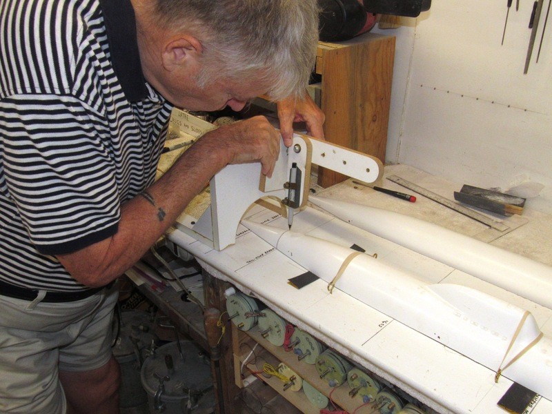
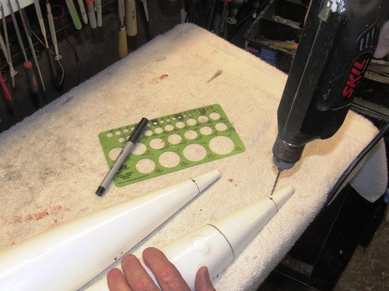
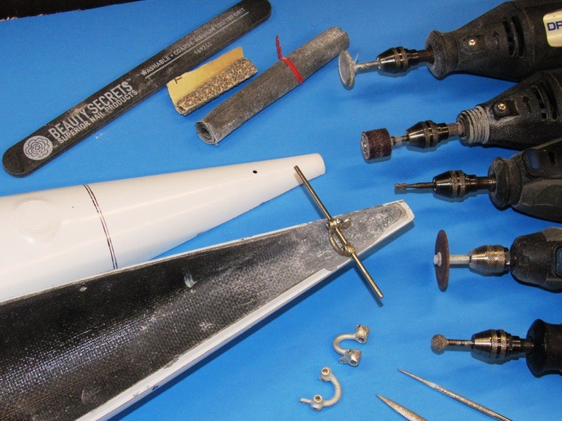
Off the marking-bench I drilled preliminary holes where the rudder and stern plane operating shafts would penetrate the stern. So identified I ground out the interior of both hull sterns to make room for the rudder and stern plane yokes, pushrods and propeller shaft. It’s the job of the yokes to operate the control surfaces, but to do so in such a way as to not interfere with each other or the centrally running propeller shaft.
Note the radial lines on the upper hull – this is where that portion of the hull will be separated, then bonded to the lower hull. Forming one-half of the Z-cut used to hold the two hull halves together. That arrangement will be made clearer in an upcoming installment.
The big deal with very narrow sterns on single-shaft submarines is the need to work out – before the two hull halves are joined – the linkage that will operate both the rudders, and the stern planes; control surfaces that are oriented ninety-degrees from one another, and in the case of the ALFA, with the two sets of control surface operating shafts falling along the same radial plane. It gets very tight in there, very fast!
To make room for the stern plane yoke (derived from a yoke originally developed for one of our r/c submarine fittings kits) a lot of excess thickness was ground away from inside the hull halves to produce the clearance needed to clear the yokes and centrally running propeller shaft.
Only after I have assured myself that the linkages and shaft work without binding or interference with one another will I remove the tail-cone half from the upper hull and bond it to the lower hull. Fat fingers and the tight confines of a tapering cone do not a happy camper make if additional fitting work has to be done because I forgot something when access was easy.
Life is hard. Life is harder if you’re stupid!
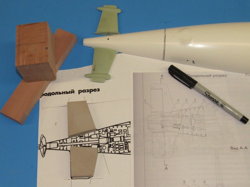
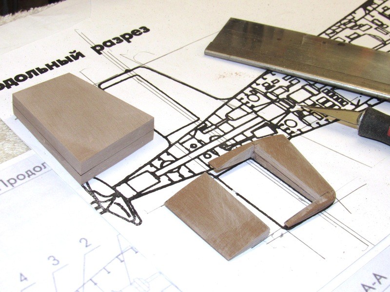
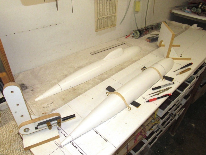
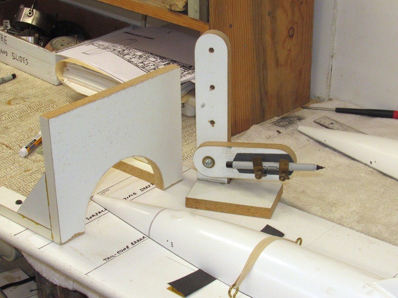
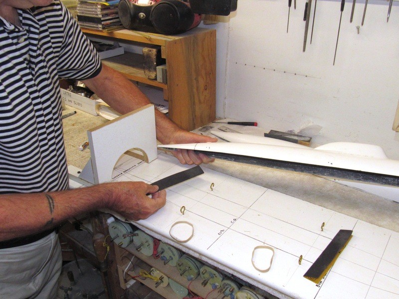
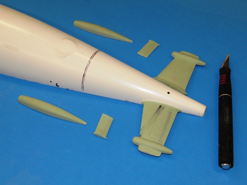
A number of years ago I had a guy in the shop for a week’s training. His graduate project was creation of masters, tools, and castings for just this very kit. He got as far – with considerable overseeing from me – as the stern plan-horizontal stabilizer, main condenser scoop, and bow plane. We ganged those masters into a single tool and after two casting, had parts for an ALFA model.
Here’s a set of those parts arrayed around the stern of the GRP 1/96 ALFA hull offered by Scale Shipyard. I’ll cut out the stern planes, integrate them with the horizontal stabilizers, and turn those parts into production masters -- functional stabilizers and stern planes. I have yet to produce the two vertical stabilizers and their rudders: tomorrow’s project.
Leave a comment:

Leave a comment: