Welcome to our forums. For the best in R/C submarine kits, components and accessories, be sure to visit the Nautilus Drydocks
If this is your first visit, be sure to
check out the FAQ by clicking the
link above. You may have to register
before you can post: click the register link above to proceed. To start viewing messages,
select the forum that you want to visit from the selection below.
We�re falling behind in reporting here, but I�ll do what I can to catch up.
Maybe I�ll just post a bunch of pictures...
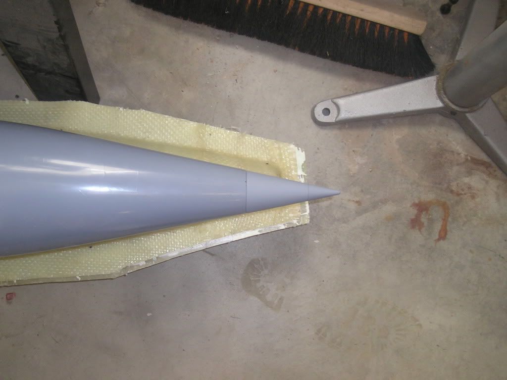
...and the cone assembly is ready for PJ installation upon it.
Alright,
So once the glass has semi-cured, I trimmed the parts with my Exacto knife...a very good time to do this. I let the parts cure all the way after that before doing any more work on them.
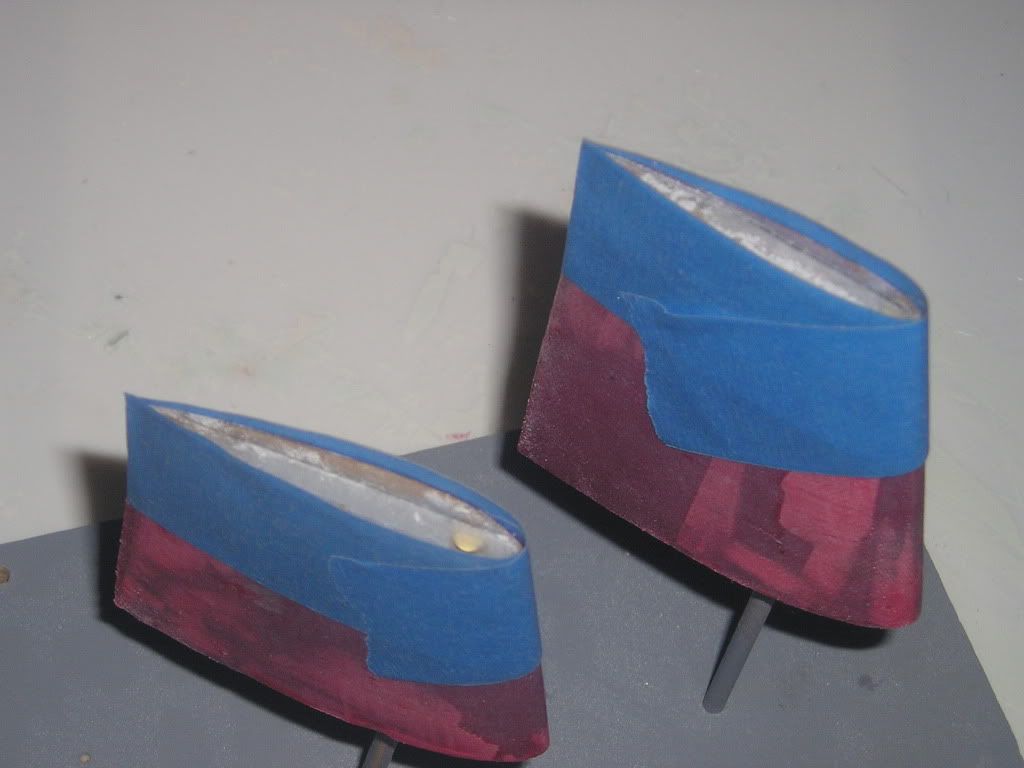
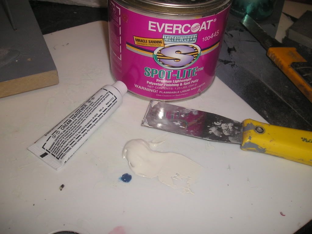
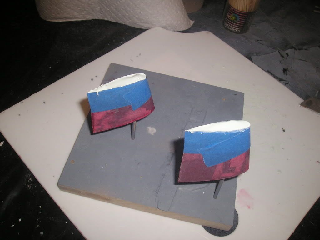
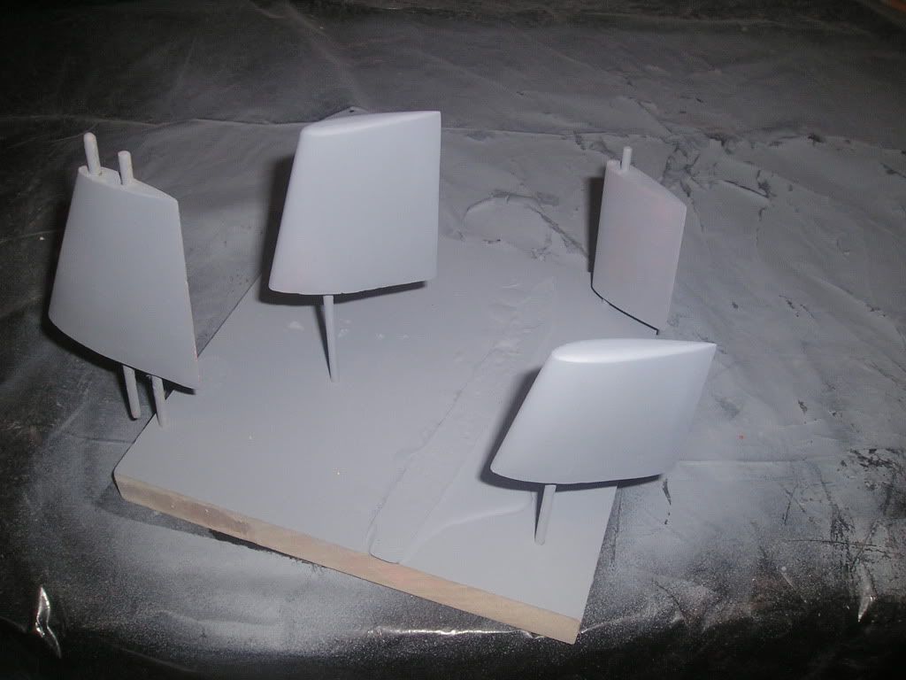
Once cure, I glue the top cap profile to the tops of the rudders. These were bolstered with baking soda soaked in CA to make an ultra hard grout. A tape dam was made around the parts and Evercoat was applied within. I removed the tape when the plastic was only partially cured and slid my knife along the profile of the caps to prevent excess sanding later. I then let the plastic cure and began the process of sculpting the shapes using a file and some sandpaper.
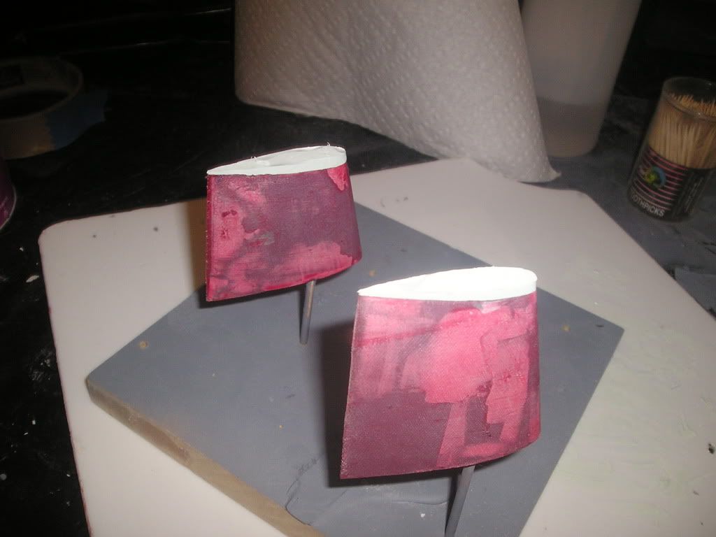
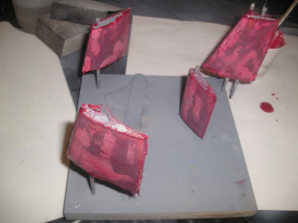
Once happy with my rough profile shape, I began the process of filling the fibreglass weave and all the minor divots using a red one part glaze. Very thin coatings are needed, and once dried I would block sand using 220. Then prime so you can see all the flaws and then repeat the whole process over and over until perfection is achieved! Not to say that I have achieved it yet with these parts...
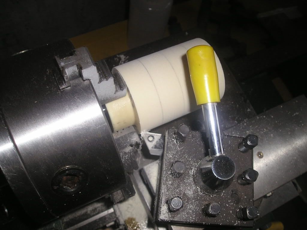
Here’s a look at the beginning of the stern cone which will have a PJ fit to it:
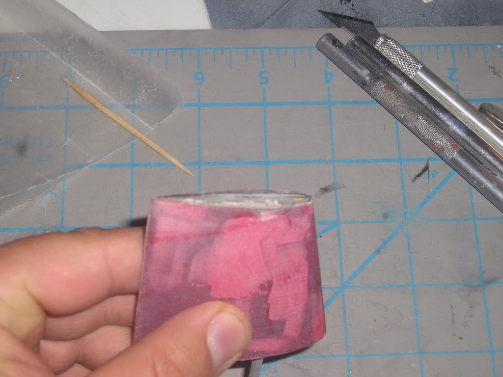
Yeah they do kinda look like candy apples! lol! Yeah, I think we have to try and make this thing be able to perform, make it somewhat enjoyable to drive for the rc submarine modeller.
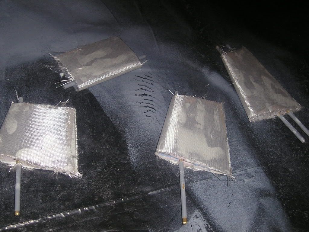
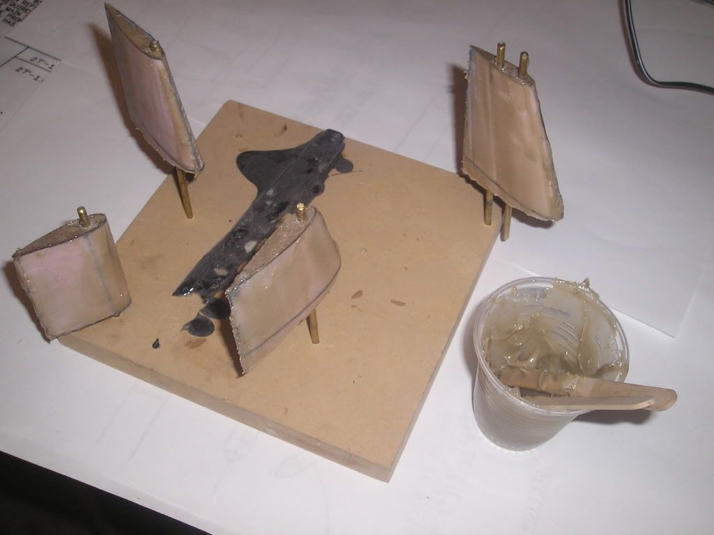
The epoxy coating is sanded down smooth and Evercoat filler is applied. This in turn is sanded down smooth, and a coat of primer is applied. Any exposed foam is eaten away by the primer, so another round of filling is needed.
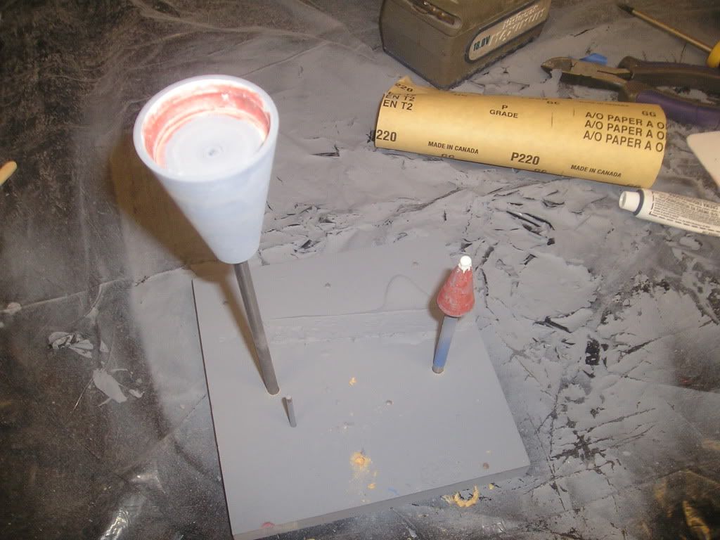
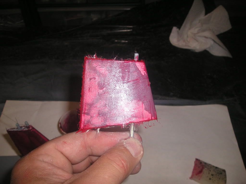
The decision is made to put a light skin of fiberglass to add strength to the fins and prevent any further foam indentations. A light coat of Super 77 is applied to the fins only and � ounce glass cloth is applied carefully so there are no wrinkles. I tinted a small batch of epoxy with my special “red oxide antifoul” pigment that I use for my fiber glass hull lay-ups. The purpose here is that when I prime the fins with grey I will be able to see how far down I’m going when sanding. I also heated the epoxy slightly with a hair drier to lessen the viscosity a bit, but not too much as to do an instantaneous cure and start my garage on fire or something. I painted the epoxy onto the fins, let soak for awhile and then squeegee the excess epoxy off with a chunk of old rtv mould rubber that I keep around for this exact purpose
Regards,
Joel
Thanks John,
Just got the walking cast on Tuesday, so I'm walking without crutches and able to fetch things for myself now. I almost feel like a real boy again!
Continuing on with appendages...
Building up steam in the project, it’s amazing how having the use of both feet again makes working with your hands easier!
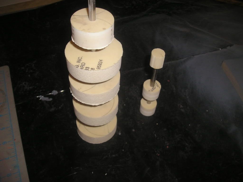
Once my Ultra blue RTV silicone cures (apparently it doesn’t take long at all – maybe an hour or so) I’ll run my hot wire along the CA-hardened top and bottom profiles and through the pink foam. Very neat, it cuts almost like a hot knife through butter. I must say that I enjoy doing this, its kinda fun really. It’s also very clean, as I don’t have mdf dust shooting up everywhere and all over my clothes and in my ears and hair. I also don’t have to wear a respirator – bonus number one!
Just some notes here; these are preliminary masters. This means that in the case of the stern planes and the bow planes I make one part and one mould and from there I can pour a few parts that I can begin to split the many parts from. In this case, the stern plane will be poured three times and from those parts I will cut away the inside stern plane, outside stern plane and the stationary stern plane. I hope this makes sense? The purpose behind this madness is to achieve perfect fitting parts down the line.
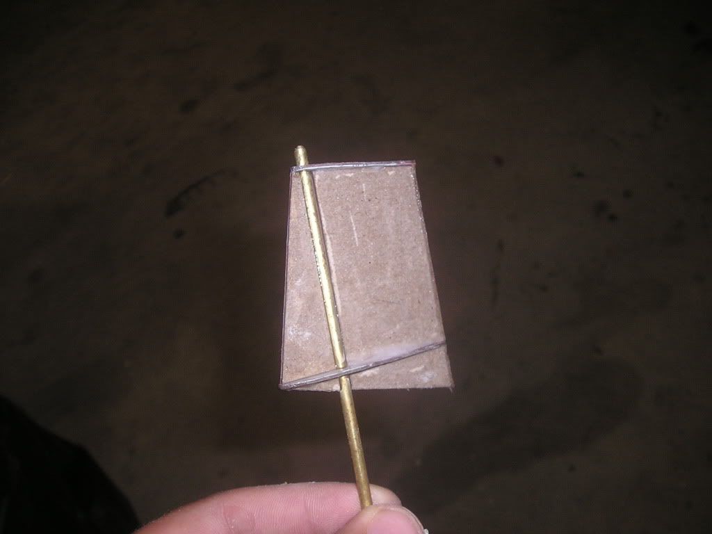
After my foam has been cut I filled some fast set epoxy with talc and spread a thin skin of the compound over the fins. This is first step in giving these fins a little strength, and to make them workable.
Regards,
Joel
Seeing as how I’m gimped it’s a little hard working with big stuff like the hull, so now I’m putting the hull to the side and I’ll start in on the small parts like the appendages.
For the fins I’m going a different route in making them than I did with my Permit. That time I went with solid MDF that I sculpted on my disc sander using jigs and various other tricks. This time I want to experiment with what could be called a “frame, foam and form” technique that implements a hot wire foam cutter. My reasons for the change? First I need a sure-fire way to get the shaft alignment 100% true as I had a hell of a time getting this right with the Permit. Second, I’m gimpy and I can do this while sitting down; I don’t have to standing at power tool station. Third, I am going to be using this technique on a larger scale for my next project, so I might as well get some practice!
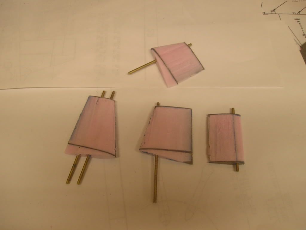
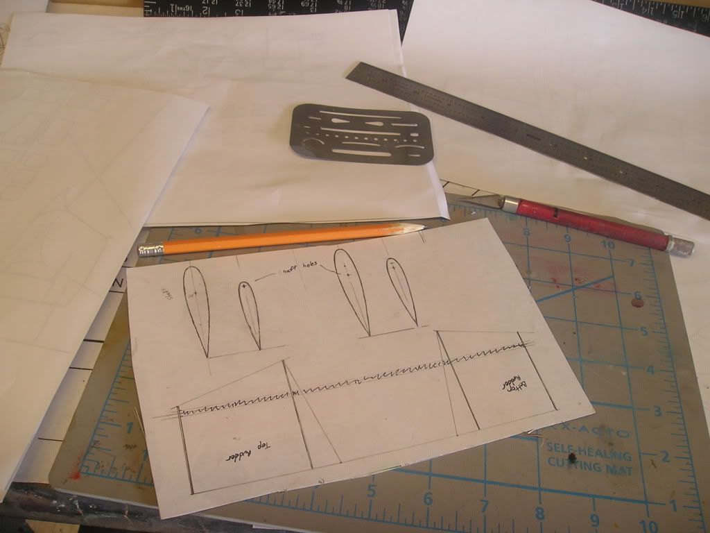
Cereal box cardboard is once again the main construction material of day. Life Cereal cardboard to be exact, I use only the best. Side, top and bottom profiles drawn on paper are glued to the cardboard using Super 77 spray on contact glue. The shapes are all very carefully cut out using an #11 Exacto and after doing so, I wick extra thin CA into the cardboard creating a very rigid, strong material that can now be filed and/or sanded. I would almost describe the marriage or Life cereal cardboard and CA as a very hard plastic. Next, I drilled a 1/8” hole in the top and bottom shapes to represent the shaft as this will be the size of rod used for that purpose.
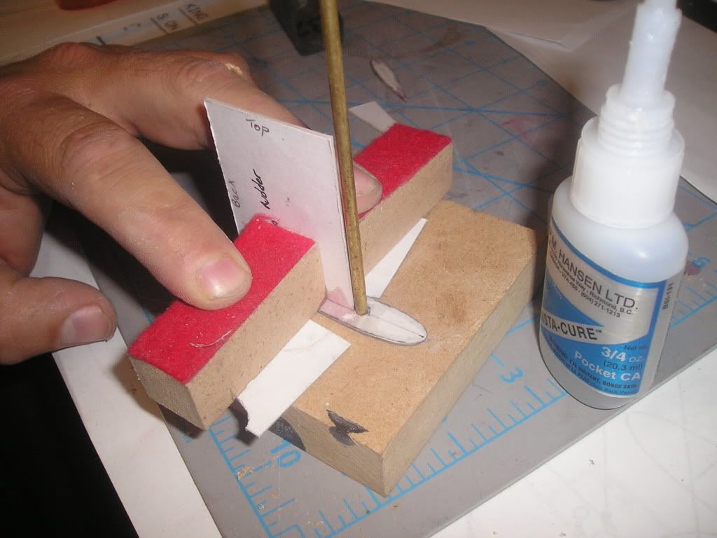
With a 1/8” rod drilled into a block of wood, the bottom profile was slipped onto the rod and the main section of the sail was CA’d in a perpendicular fashion, along the center line and exactly 90 degrees using two blocks of wood to hold the part steady while drying.
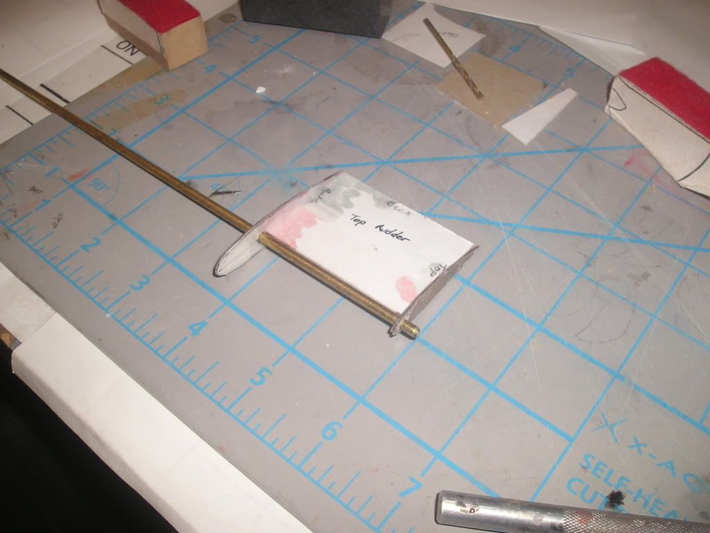
The rod is removed from the block, and the top profile is slid on. With alignment assured by matching up the back points and with the rod in the front I glued the parts together. I could then glue all the rest together and douse the whole thing in CA.
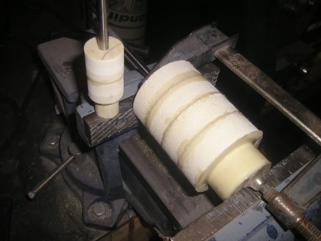
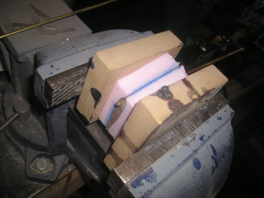
Foam blocks are fit between the frame and glued in place using Ultra Blue RTV silicone. The whole thing is sandwiched between two blocks of wood in my vise waiting to dry...
Next, we’ll form this part using a hot wire foam cutter.
Joel
Wow, I imagine with that setup the boat the manouver like a torpedo! I think for the Wolf what I might end up doing is including 2 sets of rudders...one set would be scale and another would be scale rudders encapsulated in clear plastic. Or...maybe scale rudders only with 2 piece streamlined clear rudders that would bolt on.
Not sure people would like an unscaled top rudder Joel IMHO - the lower one given it has some conjecture around it could be a tad bigger. But getting COG / COR placement and ballasting right cannot be understated.
A lower one increased in size via clear plastic or any other method, I'd be keen to test.
Originally posted by ADDINGTON
Anhedrals and their functions aside, the Seawolf in 1:1 or any other scale is no Formula One machine.
In my 1/96 version, I found that ballast weight placement and determining the exact COG were crucial. Boat was very sensitive to changes both in pitch and yaw planes.
I do not think that the presence of anhedrals are a huge obstacle to a nice handling model. Pete Piekarski's Virginia behaved very well at the Carmel SubRegatta, as good as any 1/96 LA ( pre-I ) I have seen. Anhedrals or no, still doubtful any LA, Seawolf and Virginia will approach the sports car performance of earlier SSN hullforms.
Make any sense?
Yeah it does make sense but the idea of perhaps utilising Anhedrals is not without merit.
First - after running an X fin all summer and doing a lot of surface driving (with two fins below the water), the anhedrals I would think, would act in a similar manner. The turning ease of the X fins even on the surface out manoeuvred subs of the same size and a tad shorter that had the simple cruciform setup. - Why - well for one - you have 4 surfaces in the water all turning other than 2 (dived), and 2 surfaces in the water turning rather than 1 surfaced. If the Anhedrals could be made to turn you'd have on the Seawolf 3 full surfaces (including the lower rudder) turning in surface trim, and 4 dived.
Second - using the Anhedrals eliminates the need for un-scale rudders
Third - agree with you 100% -going back to my ballasting and getting the boat light and ballasted correctly will make a big difference. I have improved on both a 1/72 Trafalgar (pump jet boat) and my X fin Collins - both the surfaced and submerged turning rates by as much as 50% by doing some basic re ballasting along the lines of what David prescribes in his Alfa cable report.
Here is a gridded up Seawolf photo I worked on with the point clearly marked as best I can estimate.
Basically if you take the overall distance of the Seawolf (regardless of scale) and measure 45% of the overall distance from the bow, that point, according to my grid exercise is where you should locate your COG / COR.
Get a sling or some sort of pivot / balance device, and ballast away around that point.
This exercise, pointed out by David, works.
Anhedrals and their functions aside, the Seawolf in 1:1 or any other scale is no Formula One machine.
In my 1/96 version, I found that ballast weight placement and determining the exact COG were crucial. Boat was very sensitive to changes both in pitch and yaw planes.
I do not think that the presence of anhedrals are a huge obstacle to a nice handling model. Pete Piekarski's Virginia behaved very well at the Carmel SubRegatta, as good as any 1/96 LA ( pre-I ) I have seen. Anhedrals or no, still doubtful any LA, Seawolf and Virginia will approach the sports car performance of earlier SSN hullforms.
Make any sense?
Wow, I imagine with that setup the boat the manouver like a torpedo! I think for the Wolf what I might end up doing is including 2 sets of rudders...one set would be scale and another would be scale rudders encapsulated in clear plastic. Or...maybe scale rudders only with 2 piece streamlined clear rudders that would bolt on.
A swivelling nozzle/shroud would give exceptional manoeuvrability. Dave Jacques did this with his Resolution class back in the 80's, he made it tilt too, but found that made things a bit too lively.
One way or another, I'm going to try to improve what I know will be poor handling.
Joel
Yes - and after running all of last summer Rankin with x fins, I might have ago Joel when I get mine of sticking some bearings through the anhedrals as secondary rudder system - heck on the bench you won't know. A simple opposing system will render both port and starboard anhedrals operating in union for extra rudder surface area....BUT to begin with I'll just try nailing the ballasting right COG on COR and keeping her light. The 3.5" WTC will help too.


Leave a comment: